GX-900
GX-900
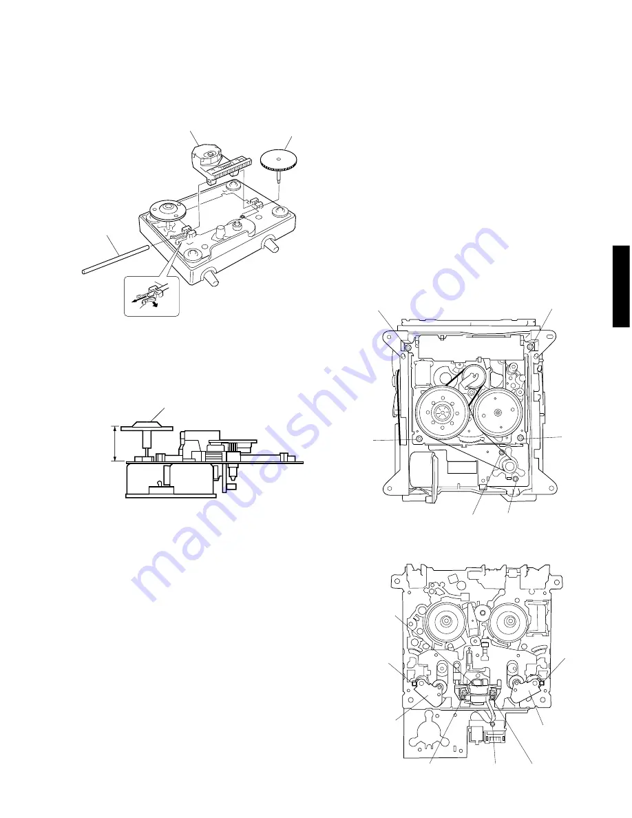
Fig. 15
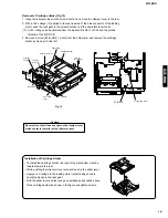
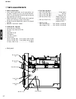
Disc Table
19.4mm
Fig. C
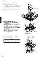
Pick-up Head
Gear A
Sled Shaft
Sled Shaft
Stopper
Fig. 13
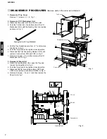
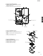
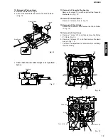
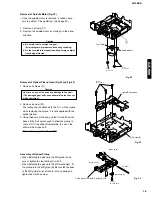
11. Removal of Cassette Mechanism
Remove 4 screws (
!9
) and then pull out the Cassette
Mechanism in Fig. 14.
12. Removal of Main Motor
Remove 2 screws (
@0
) in Fig. 14.
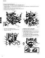
13. Removal of Pinch Roller
Detach the hook and then remove the Pinch Roller
in Fig. 15.
14. Removal of Head Ass’y
a. Remove 1 screw (
@1
) and then remove the Relay
P.C.B. in Fig. 15.
b. Remove 2 screws (
@2
) and then remove the Head
Ass’y in Fig. 15.
*
Perform the adjustment of azimuth after installing
the Head Ass’y.
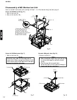
10. Removal of Pick-up Head
a. Remove the Gear A in Fig. 13.
b. Pull out the Sled Shaft and remove the Pick-up Head
in Fig. 13.
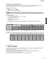
●
Check that the disc table height is as specified
below.
Fig. 14
12
!9
!9
!9
!9
@0
@0
@1
@2
@2
Pinch Roller (L)
Pinch Roller (R)
Hook
Hook
Head Ass'y
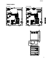
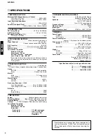
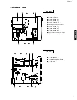
Summary of Contents for GX-900
Page 103: ...GX 900 GX 900 ...


