GX-900
GX-900
14
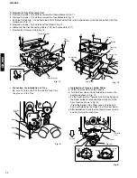
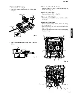
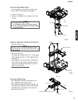
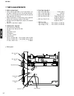
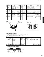
Removal of Cartridge Holder (Fig.19)
1. Open the roller arm lever in the arrow direction and move the clamper lever to the rear.
2. With a +5V voltage (*2) applied to the red line side of the blue connector of the loading
motor, push the rack gear in the arrow direction until the cam plate lever clicks.
(*2) A +5V voltage can be obtained from the pluspol (D6.5/5V) of C35 and the ground
terminal of the MD P.C.B.
3. Remove a screw (B1 and B2, 1 each) from the holder arm and remove the cartridge
holder by moving it to the left.
Slider Lever
Cartridge Holder
Clamper
Lever
Rack Gear
Roller Arm Lever
Loading
Motor
Cam Plate
Lever
(B1) x1
Ø1.7x5mm
(B2) x1
Fig.19
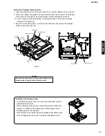
Caution
Be careful so that oil does not get on the clamper lever
which contacts the roller of the roller arm lever.
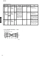
Installation of Cartridge Holder
• To install the cartridge holder, the rack of the mechanism must be
lowered toward the rear.
• While pushing the roller arm lever outward, push in the slider lever.
• Apply a +5V voltage to the loading motor (until clicking sound is
heard) and push in the rack gear.
• With the slider lever and the rack gear installed as described above,
fit the cartridge holder as shown in the figure and tighten screws.
C35
Pluspol (D6.5/5V)
P.C.B. MD
Summary of Contents for GX-900
Page 103: ...GX 900 GX 900 ...


