
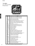
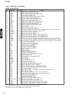
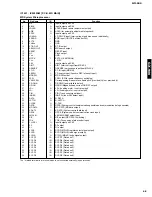
Fig. 27
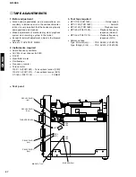
MECHANISM ADJUSTMENT
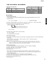
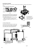
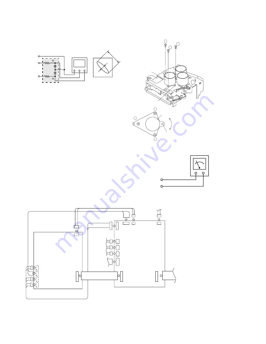
When making adjustment, be sure to connect an extension cable for servicing and an expansion P.C.B. as shown in
Fig.29.
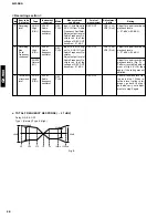
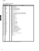
Oscilloscope
GND CH1
CH2
X
Y
IC1101 No.43 pin
GND (TP1125)
IC1101 No.26 pin
EOUT (TP1129)
IC1101 No.25 pin
FOUT (TP1130)
100K
470p
470p
a
b
Lissajous waveform
a:b = Within 4:1
100K
1
2
3
1
2
3
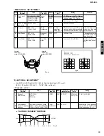
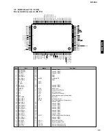
Adjustment hole
Spindle motor
Spindle motor
Adjustment hole
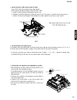
After performing automatic adjustment in the AUTO mode
selected from the test mode by using a high reflecting MD
disc (COMPLETE status on display), adjust the EOUT to
FOUT Lissajous waveform (x-y).
1. Loosen 3 screws of the spindle motor a little and make
adjustment while watching the Lissajous waveform.
2. After adjustment, tighten screws in the order of (
q
), (
w
)
and (
e
).
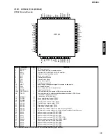
Fig. 26
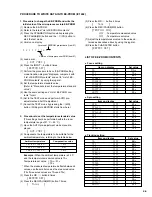
2. Jitter verification method
Jitter meter
IC1201 No.1 pin (TP1201)
EFMMON
(TP1125)
GND
Fig. 28
After performing automatic adjustment in the AUTO mode
selected from the test mode by using a low reflecting MD
disc, confirm the jitter in the pit continuous reproduction
mode and the groove continuous reproduction mode.
FFC for 5P extension
TX946190
Connector for 2P extension
TX946200
CN1602(Rear face)
CN1601(Rear face)
CN1603(Rear face)
CN1604(Rear face)
CN1300(Rear face)
CN1101
MD Main P.C.B.
Connector for 6P-2P extension
TX946210
FFC for 28P extension
TX946220
Extension P.C.B. for servicing
(TX946230)
Install an Extension P.C.B. for servicing
to the mechanism.
From optical pickup
From magnetic head
From motor
Mechanism
SW P.C.B.
Fig. 29
(Externally attached)
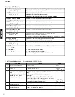
1. Optical pickup rating inspection method
Check the Lissajous wave-
form while adjusting the
installation position by using a
screwdriver in the adjustment
hole in the spindle motor.
(See page 69)
(See page 69)
35
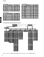
Summary of Contents for GX-900
Page 103: ...GX 900 GX 900 ...