GX-900
GX-900
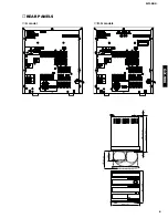
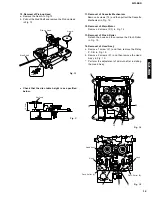
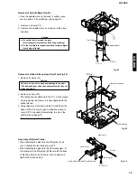
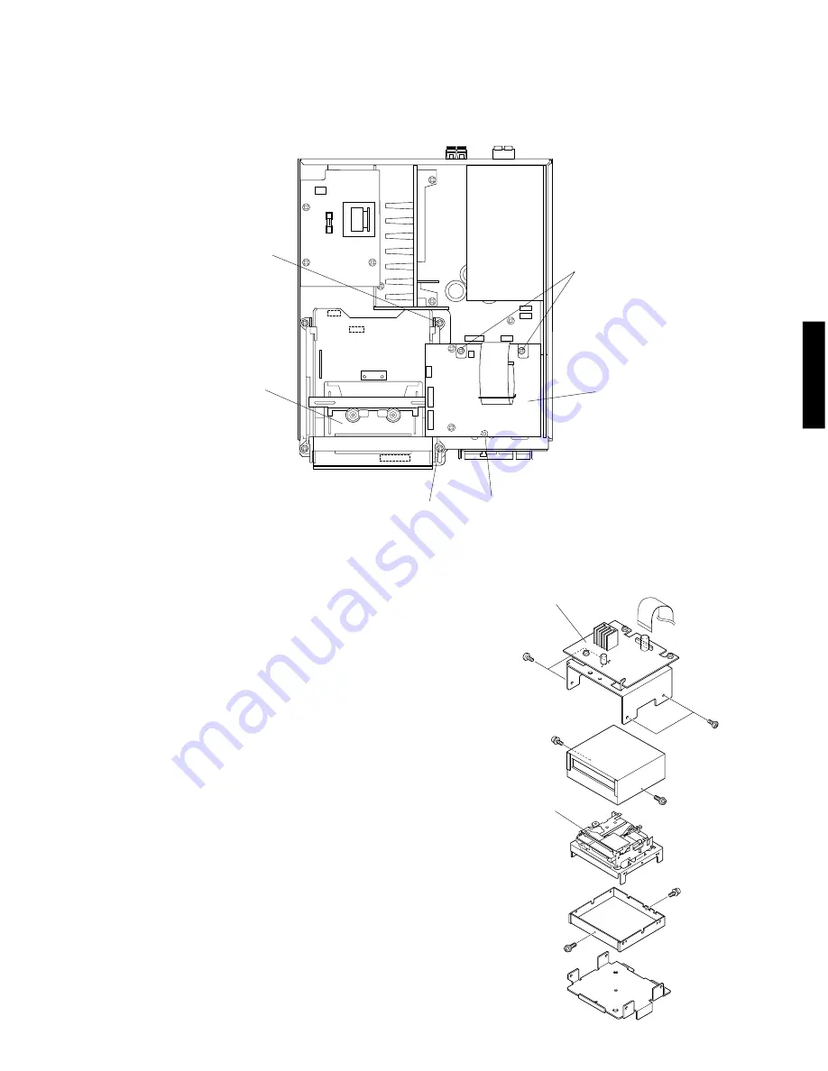
Fig. 3
8
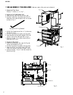
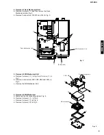
4. Removal of Deck Mechanical Unit
a. Remove 4 screws (
t
) and then remove the Deck
Mechanical Unit in Fig. 3.
b. Remove 3 connectors ( W2, W3 and W4 ) in Fig. 3.
t
t
t
t
Deck Mechanical Unit
W3
W2
W4
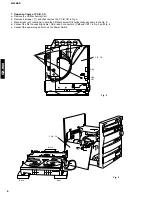
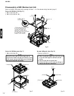
5. Removal of MD Mechanical Unit
a. Remove 3 screws (
y
) in Fig. 3 and 1 screw (
u
) in
Fig. 1.
b. Remove 4 connectors ( CB1, CB3, CB4 and CB5 ) in
Fig. 3.
c. Remove the MD Mechanical Unit.
y
(Bottom side)
y
MD Mechanical Unit
CB3
CB5
CB1
CB4
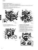
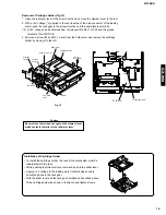
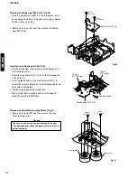
6. Removal of MD Mechanism
a. Disconnect the flat connecting cable in Fig. 4.
b. Remove 4 screws (
i
) in Fig. 4.
c. Remove 2 screws (
o
) in Fig. 4.
d. Remove 2 screws (
!0
) in Fig. 4.
P.C.B. MD
MD Mechanism
Fig. 4
i
i
o
o
!0
!0
Flat connecting cable
Summary of Contents for GX-900
Page 103: ...GX 900 GX 900 ...


