


E-46
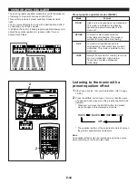
The Sound Field Processor built into this system presents you with the ambience of an actual concert hall etc. by adding effects as
sonic reflections or reberverations that create the sound environment of a hall etc. This system provides preset sound field
programs shown below. You can enjoy an excellent audio sound field by selecting one of them, and adding desired adjustments.
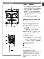
This system incorporates a Dolby Pro Logic Surround decoder for multi-channel sound reproduction of Dolby Surround encoded
video sources. The operation of the Dolby Pro Logic Surround decoder can be controlled by selecting a corresponding sound field
program.
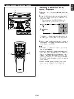
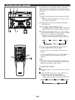
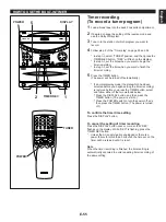
USING SOUND FIELD PROCESSOR
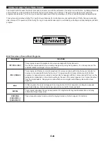
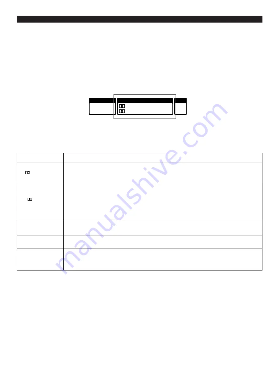
Brief Overview of Sound Field Programs
PROGRAM
PRO LOGIC
3 STEREO
HALL
ARENA
KARAOKE
(KARAOKE L)
(KARAOKE R)
FEATURE
This program is used for playback of sources encoded with Dolby Surround.
Sounds are reproduced as movie creaters designed by using five speakers. You can experience the
dramatic realism and impact of a movie theater.
This program is effective not only for playback of sources encoded with Dolby Surround, but also for
sources not encoded with Dolby Surround or TV programs with 2-channel stereo sound. With this
program, 2-channel stereo sound is converted into 3-channels (left front, center and right front), so the
dialogs are emphasized on the center position by the use of the center speaker. As no sound is output
from the rear speakers, this program is also effective in a simple Audio/Video system without rear
speakers.
In this program, the center will appear to be deep behind the front speakers, creating an expansive
large hall ambience. Orchestra and opera music are suited for this sound field.
This program simulates the sound environment of a big hall with long reverberation time and many
reflections of high frequencies.
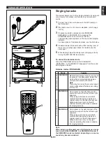
These are audio output modes useful for singing Karaoke. (Refer to page 51 for details.)
MUSIC
ROCK BLUES
RAP JAZZ
USER
1 2
3 4
PROGRAM
PRO LOGIC HALL ARENA
3 STEREO KARAOKE L R


