background image

– 53 –

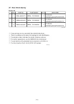
Parts List

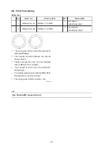
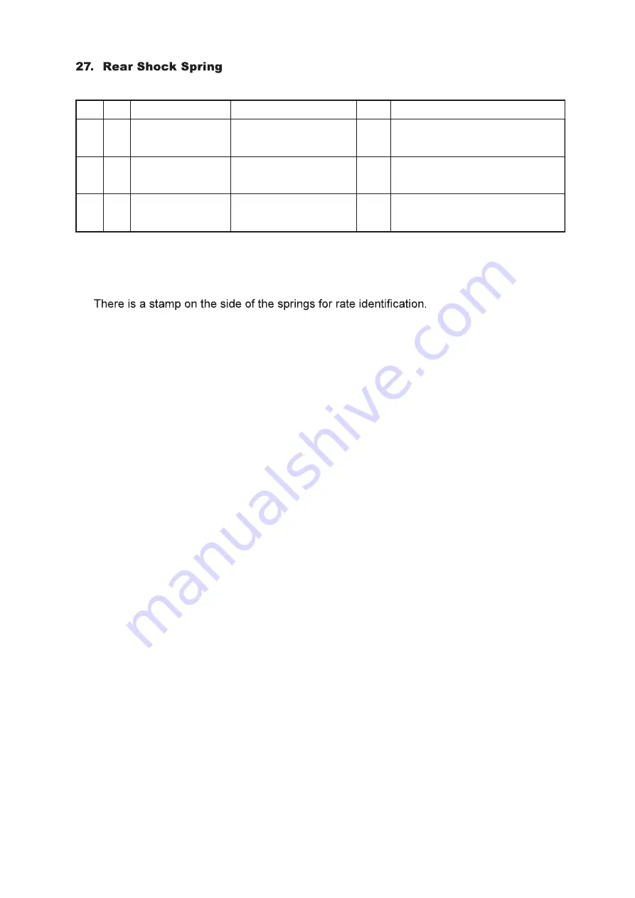
These springs can be used with the standard absorbers.


The stamp number indicates the length, diameter and rate.

For spring replacement, see the BN6 STD. Service Manual.

The spring rate of the standard rear suspension is 103 N/mm.

The free length is 152.9 mm for STD / KIT springs.

R6180501Rev

No.

PART No.

PART NAME

Q'TY

REMARKS

1

BN6-22222-75

SPRG., Rr. SHOCK

1

108 N/mm
Identifying stamp:152.9-56-108

2

BN6-22222-80

SPRG., Rr. SHOCK

1

113 N/mm
Identifying stamp:152.9-56-113

3

BN6-22222-85

SPRG., Rr. SHOCK

1

118 N/mm
Identifying stamp:152.9-56-118

R6EN181106Rev

Summary of Contents for GYTR YZF-R6 2022

Page 1: ......

Page 2: ...ly requested not to use them on public roads are subject to change without notice for improvement Parts List Symbols The star mark means that the part is included in the kit set and is a genuine Yamaha part Therefore you can easily purchase the part at any Yamaha part dealer when necessary The circle mark means that although the part is included in the kit set it can also be purchased individually...

Page 3: ...embly 2C0 1351A 70 28 15 Air Funnel Set BN6 1440B 70 for SS 29 16 Air Funnel Set BN6 1440B 80 for STK 31 17 AIS Plug Set 13S A4890 70 35 18 Clutch Spring Set 2C0 A6330 70 37 19 Friction Plate Set 2C0 A6321 70 38 20 Slipper Clutch Setting Set 4B1 A6377 70 39 21 Transmission Gear 42 22 Mission Maintenance Set 2C0 A7000 70 46 23 Drive Sprocket 49 24 Sprocket Nut Set 2C0 A7463 70 50 25 ACM Set 2C0 F14...

Page 4: ...nding 13 7 1 Depending on the thickness of the head gasket 13 2 1 Valve t iming event angle INT 110 105 105 EXT 115 110 110 Squish height INT 0 65 0 75mm 0 65 0 75mm 0 65 0 75mm EXT 0 95 1 00mm 0 95 1 00mm 0 95 1 00mm Clearance between valve and piston minimum INT 1 05 mm ATDC 12 1 05 mm ATDC 12 1 15 mm ATDC 12 EXT 1 62 mm BTDC 12 1 62 mm BTDC 12 1 80 mm BTDC 12 valve tappet clearance INT 0 12 0 1...

Page 5: ...n if it is not assembled with the ECU BN6 8591A 70 71 A0 A1 A2 G0 B0 B1 of the kit The combination of this wire harness and ECU can only be used with 17 to 22 models in advance Before starting assembly remove the coupler of the main switch Be sure to connect the Hydraulic unit assy to the wire harness The ABS does not function when using the KIT ECU but every electronic control does not work witho...

Page 6: ...the position where the EXUP motor was removed you need to perform processing operation Refer to the following images to perform processing operation 3 As illustrated install the removed rectifier regulator using the provided bracket regulator etc TIP To install the Hydraulic unit assy you need to perform processing operation to create the installation space ...

Page 7: ... 4 TIP Fix the Hydraulic unit assy with the rubber band located at the position indicated by an arrow in the following image the size of the Hydraulic unit assy ...

Page 8: ...owing parts Check the position of the following parts WIREHARNESS ASSY MAIN SW SW HANDLE L 1 2 POWER SUPPLY 2 c TIP c Fix the harness that will be connected to SW HANDLE L 1 2 etc to 6 BLKT REGULATOR 1 using cable ties 9 Assemble the wire harness to the chassis referring to the following materials ...

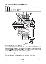
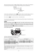
Page 9: ...2 3 4 WATER TEMP SENSOR RR WHEEL SENSOR GEAR PO SENSOR VI MOTOR NEUTRAL SW LIGHT SW OIL SW SHIFT SW CRANK SHAFT SENSOR WIRE SUBLEAD 1 4 WIRE LEAD for FUEL PUMP WIREHARNESS ASSY SELECT SW PRESSURER SENSOR ABS ECU Hydraulic unit assy 4 5 6 7 8 9 WIRE TH INJECTOR 10 c d e c d e Connect each wire lead to the following parts Check the position of the following parts ...

Page 10: ... 7 WIREHARNESS ASSY 11 MAIN FUSE ST RELAY 1 RELAY ASSY 14 FUSE BOX 1 SERVICE TOOL ECU LEAN ANGLE SENSOR POWER SUPPLY TAIL LIGHT 11 12 13 14 15 16 17 18 19 Connect each wire lead to the following parts ...

Page 11: ... 8 1 2 BN6 82590 70 WIRE HARNESS ASSY Details ...

Page 12: ... 9 1 BN6 82386 70 WIRE SUB LEAD for TH INJECTOR Details BN6 83553 70 WIRE LEAD for METER Details ...

Page 13: ... the owner s manual of the STD 3 Pit road limiter Switch to any direction to enable the limiter function Press to disable the limiter function 1 Starter switch Engine stop switch Same as the STD For details refer to the owner s manual of the STD 2 Mode switch Same as the STD For details refer to the owner s manual of the STD ...

Page 14: ... akrapovic com en intro returnUrl 2F No PART No PART NAME Q TY REMARKS 1 BN6 8591A 71 ECU for SS Following WSS rule 1 2 B3L 2818Y 73 CD 1 YMS SOFT MANUAL No PART No PART NAME Q TY REMARKS 1 BN6 8591A A2 ECU for STK 1 2 B3L 2818Y 73 CD 1 YMS SOFT MANUAL Parts List BN6 8591A A2 No PART No PART NAME Q TY REMARKS 1 BN6 8591A B1 1 2 B3L 2818Y 73 CD 1 YMS SOFT MANUAL Parts List BN6 8591A B1 R6EN20220215...

Page 15: ...de by inserting and removing the 2 pole coupler 7 of the kit harness When the coupler is connected it becomes KIT STK air funnel BN6 1440B 80 mode When the coupler is disconnected it becomes STD air funnel mode When shipped the coupler is connected BN6 82590 70 WIREHARNESS ASSY 7 R6E20220202Rev ...

Page 16: ... ECU air funnel and wire harness except for the following combinations PARTS COMBINATION TABLE MODEL CAMSHAFT IN CAMSHAFT EX VALVE SPRING AIR FUNNEL SET ECU WIRE HARNESS SET 2017 2018 2019 2020 2021 2022 2C0 12171 73 2C0 12181 71 2C0 A2110 70 BN6 1440B 70 MGC A300908 10 with MGC A300912 00 BN6 8591A 70 BN6 8591A 71 BN6 F2590 70 MODEL SHAFT CAM1 INT SHAFT CAM 2 EXT VALVE SPRING AIR FUNNEL SET ECU W...

Page 17: ...ndows 10 supported This cable connects the kit wire harness to the personal computer on which YEC FI Matching System YMS is installed Please see the YMS manual for instructions on how to use YMS driver Refer to the USB Driver Installation Manual provided on the CD for details on how to install the USB driver R6EN20191201 ...

Page 18: ...fault Ground fault Open circuit supply fault Deviation fault Incompatibility Incompatibility Ground fault Open circuit supply fault Ground fault Open circuit supply fault Ground fault Open circuit supply fault Disabled Disabled Disabled Disabled Disabled No signals Abnormity Writing error Abnormity Abnormity Checksum error Communication fault between CPUs Sub CPU ROM RAM abnormity Main CPU operati...

Page 19: ...ANUAL for the vehicle or the explanation of the store application in addition to this manual R6180501Rev Parts List No PART No PART NAME Q TY REMARKS 1 2KS 85810 72 CCU ASSY 1 dedicated software embedded 2 2KS 88107 00 GPS unit 1 3 2KS 85721 71 Sub harness 1 Application Download from App Store Google Play Store Components CCU ASSY dedicated software embedded GPS unit Sub harness Application Downlo...

Page 20: ...blet and CCU be sure to write down the number TIP When using it for the first time check if the GPS icon lights up on the meter before riding It may take about 10 minutes for GPS positioning even in an outdoor location NOTICE If GPS positioning is not available it will Download the application onto the tablet TIP For Android visit Google Play Store and For iOS visit App Store and download Y TRAC Y...

Page 21: ...rack See Fig 2 Y TRAC for iOS version CCU While riding After riding Download the logging data from the CCU Y TRAC CCU Display the logging data with map Y TRAC Internet Usage Fig 1 Fig 2 TIP When connecting the tablet to the network select CCU when communicating with the CCU or Internet when displaying the map according to the use Connecting to the CCU Label on the CCU See Fig 3 Network name SSID Y...

Page 22: ... be changed according to the specification of the installed sensor To change the display value tap AIN Setting Example 1 When the following is stated in the sensor s manual AF value voltage x 1 6 10 Factor 1 6000 10 0000 Min Y axis 10 00 Max Y axis 20 00 Min Y axis and Max Y axis can be any given values Example 2 When the following is stated in the sensor s homepage AF value output voltage x 14 7 ...

Page 23: ...tion procedure Short press the SELECT switch and RESET switch simultaneously to start the lap timer colon and period will blink when the lap timer starts up This operation is required each time after the main switch is set to ON R6180501Rev TIP Regardless of the meter setting lap data will be recorded in the logging data when line passing is detected RESET button SELECT button R6180501Rev ...

Page 24: ... 07001 NUT 24 6 4SV 12119 00 SEAL VALVE STEM OIL 48 7 2C0 12213 00 GASKET TENSIONER 3 8 2C0 13414 70 GASKET STRAINER 3 ANTI STICK TYPE 9 2C0 15451 70 GASKET CRANKCASE COVER 1 3 ANTI STICK TYPE 10 2C0 15461 70 GASKET CRANKCASE COVER 2 3 ANTI STICK TYPE 11 2C0 15456 70 GSKT 1 3 ANTI STICK TYPE 12 93102 35017 SEAL OIL 3 FOR DRIVE AXLE 13 90151 06024 SCREW CROSSRECESSED COUNTERSUNK 9 FOR BEARING HOUSI...

Page 25: ...is needed during installation on the following points 1 The tightening torque is 12 15 N m 1 2 1 5 kgf m 2 When not checking the torque tighten by rotating through 30 after manual tightening in the case of new plugs When reusing plugs tighten by rotating through 15 Parts List Angled ground strap Type 13S R373A 70 No PART No PART NAME Q TY REMARKS 1 13S 1119C 70 PLUG SPARK 4 NGK R0373A 10 ...

Page 26: ... the cylinder head commonly called the dome volume as follows Measuring equipment 1 Burette 2 Clear plastic plate 3 Oil 3 1 mixture of torque converter oil and white gasoline 4 Vaseline to seal the valve and plastic plate Measurement method 1 Tighten a regulation spark plug to the regulation torque in the cylinder head to be measured 2 Set so that the alignment surface of the combustion chamber is...

Page 27: ...ISTON 4 4 93450 16159 CIRCLIP 8 Parts List No PART No PART NAME Q TY REMARKS 1 13S 11650 01 CONN ROD ASSY 4 ceed 2g and combine them so that the small end weights are uniform by Yamaha s measuring method R6EN20181106 Parts List No PART No PART NAME Q TY REMARKS 1 2C0 11411 00 CRANKSHAFT 1 Select a crankshaft with good balance ...

Page 28: ...xpected and more over the engine may be damaged When using this camshaft use the valve spring set 2C0 A2110 70 INT 2C0 12171 73 Parts List No PART No PART NAME Q TY REMARKS 1 2C0 12171 73 SHAFT CAM 1 1 INT No PART No PART NAME Q TY REMARKS 2 2C0 12181 71 SHAFT CAM 2 1 EXT No PART No PART NAME Q TY REMARKS 3 2C0 12176 80 SPROCKET CAM 1 1 INT No PART No PART NAME Q TY REMARKS 4 2C0 12177 80 SPROCKET...

Page 29: ...or 2C0 12181 71 EXT Identifying color Yellow 3 2C0 12117 70 RET VALVE SPRING 16 exclusively for the kit cam shaft and used in combination NOTICE When using this valve spring use the camshafts 2C0 12171 71 2C0 12171 72 2C0 12171 73 and 2C0 12181 71 Do not use the camshaft valve spring ECU air funnel and wire harness except for the following combinations ...

Page 30: ...VALVE SPRING AIR FUNNEL SET ECU WIRE HARNESS SET 2017 2018 2019 2020 2021 2022 2C0 12171 73 2C0 12181 71 2C0 A2110 70 BN6 1440B 70 MGC A300908 10 with MGC A300912 00 BN6 8591A 70 BN6 8591A 71 BN6 F2590 70 FOR STK PARTS COMBINATION TABLE MODEL SHAFT CAM1 INT SHAFT CAM 2 EXT VALVE SPRING AIR FUNNEL SET ECU WIRE HARNESS SET 2017 2018 2019 2020 2021 2022 Use with standard air funnel BN6 8591A A0 BN6 8...

Page 31: ...ing it cut The part has a collar to prevent over tightening In normal cases the part will not be tightened till it reaches to the collar Just manually tighten it Make sure to put a new band through a M4 x 0 7 tap before using it 14 Parts List No PART No PART NAME Q TY REMARKS 1 2C0 13300 70 OIL PUMP ASSY 1 This pump is capable of a larger discharge than the STD counterpart ...

Page 32: ...REMARKS 1 BN6 14479 70 FUNNEL 1 2 BN6 14469 70 FUNNEL 1 1 3 BN6 1446C 70 FUNNEL 2 1 Installation 1 Remove the STD funnel funnel 2 Fit the part to the cutouts and combine the funnel parts 3 Attach the funnel to the air box Parts List ...

Page 33: ...0 8591A 90 2C0 8591A 91 13S F82590 70 13S F82590 71 2009 MGC A300908 00 2010 2C0 12171 72 MGC A300908 10 MGC A300912 00 2011 2C0 12171 73 2C0 8591A 92 2C0 8591A 93 2C0 8591A 94 2012 2013 2014 2015 2016 FOR SS MODEL CAMSHAFT IN CAMSHAFT EX VALVE SPRING AIR FUNNEL SET ECU WIRE HARNESS SET 2017 2018 2019 2020 2021 2022 2C0 12171 73 2C0 12181 71 2C0 A2110 70 BN6 1440B 70 MGC A300908 10 with MGC A30091...

Page 34: ...9 10 FUNNEL 2 Stamp 13S 10 4 13S 14490 10 SHAFT ASSY 1 Rod shape Straight Installation 1 Remove the STD funnel and the SHAFT ASSY SHAFT ASSY 2 Remove the below parts from the STD funnel 1 LEVER 1 2 LEVER 2 3 BUSH 1 4 BUSH 2 5 COLLAR 6 GROMMET 7 RUBBER SEAL Parts List Acceleration characteristics change by installing this Air Funnel Set R6E20220202Rev ...

Page 35: ...funnel Install the BUSH 1 4 pieces and the RUBBER SEAL to the FUNNEL Install the BUSH 2 4 pieces to the FUNNEL 1 and the FUNNEL 2 TIP Align the cut out positions of the BUSH 1 and the LEVER 2 BUSH1 Install the BUSH 1 1 piece to the center of LEVER 2 R6E20220202Rev ...

Page 36: ...l the LEVER 1 and the LEVER 2 to the FUNNEL Install the FUNNEL 1 and the FUNNEL 2 FUNNEL 1 FUNNEL 2 TIP Install the COLLAR and the GROMMET to the FUNNEL 1 and the FUNNEL 2 5 Install the SHAFT ASSY R6E20220202Rev ...

Page 37: ... A300912 00 2011 2C0 12171 73 2C0 8591A 92 2C0 8591A 93 2C0 8591A 94 2012 2013 2014 2015 2016 FOR SS MODEL CAMSHAFT IN CAMSHAFT EX VALVE SPRING AIR FUNNEL SET ECU WIRE HARNESS SET 2017 2018 2019 2020 2021 2022 2C0 12171 73 2C0 12181 71 2C0 A2110 70 BN6 1440B 70 MGC A300908 10 with MGC A300912 00 BN6 8591A 70 BN6 8591A 71 BN6 F2590 70 FOR STK MODEL SHAFT CAM1 INT SHAFT CAM 2 EXT VALVE SPRING AIR FU...

Page 38: ...late 5SL 1482L 70 in replacement of the cap Apply liquid gasket to the plate 4 Remove the cylinder head cover and the four collars fitted to the cover Install the PIN 93608 16M16 5 After removing the hose connected to the air cleaner case from the air cut valve assembly open the upper case of the air cleaner case and insert the PLUG 90336 10020 into the hole where the hose was connected ...

Page 39: ... 36 ...

Page 40: ... 37 Parts List No PART No PART NAME Q TY REMARKS 1 2C0 16334 70 SPRING CLUTCH 2 6 Identifying color Green The clutch spring should have a bigger mounting load than standard ...

Page 41: ... 38 Parts List No PART No PART NAME Q TY REMARKS 1 5EB 16321 72 PLATE FRICTION 1 9 Compared to STD the friction plate enhances durability and operation ...

Page 42: ...ugh adjusting 2 the number of SHIMs set up for the kit a the number of springs b the whole thickness of the clutch plate and the strength of c spring set up for the kit of the slipper clutch setting set Recommended setting method To begin with the dimensions of the clutch are re set to the standard values For details please refer to the service manual published from YAMAHA MOTOR CO LTD If you atta...

Page 43: ...wing table Clutch plate 1 PART No Thickness 168 16325 00 1 6 mm 0 063 in 3J2 16324 00 2 0 mm 0 079 in STD 168 16324 00 2 3 mm 0 091 in Clutch plate 2 PART No Thickness 3J2 16324 00 2 0 mm 0 079 in STD 168 16324 00 2 3 mm 0 091 in NOTICE When decreasing the number of a spring to two the caution should be taken to surely use three pieces of SHIMs for the slipper clutch setting set If its number bein...

Page 44: ... 41 ...

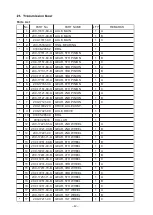
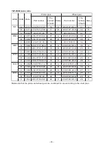
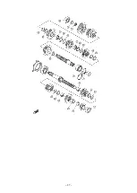
Page 45: ...C0 17121 00 GEAR 2ND PINION 1 C 8 2C0 17402 70 DRIVE AXLE ASSY 1 9 2C0 17421 00 AXLE DRIVE 1 10 93305 20509 BRG 1 11 90387 25016 COLLAR 1 12 2C0 17221 81 A GEAR 2ND WHEEL 1 A 12 2C0 17221 90 B GEAR 2ND WHEEL 1 B 12 2C0 17221 00 GEAR 2ND WHEEL 1 C 13 2C0 17261 71 A GEAR 6TH WHEEL 1 A 13 2C0 17261 80 B GEAR 6TH WHEEL 1 B 13 2C0 17261 90 C GEAR 6TH WHEEL 1 C 14 2C0 17241 80 A GEAR 4TH WHEEL 1 A 14 2C...

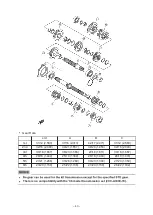
Page 46: ...20 1 950 32 16 2 000 3rd 30 18 1 667 36 23 1 565 29 18 1 611 30 18 1 667 4th 26 18 1 444 25 18 1 389 26 18 1 444 28 19 1 474 5th 27 21 1 286 33 26 1 269 30 23 1 304 27 20 1 350 6th 23 20 1 150 25 22 1 136 23 20 1 150 26 22 1 182 NOTICE There is no compatibility with the 06 model transmission set 2C0 A7400 70 ...

Page 47: ...3 A 2C0 17231 80 A 36 A B 1 611 2C0 17131 71 B 18 B 2C0 17231 70 B 29 B C 1 667 2C0 17131 90 C 18 C 2C0 17231 90 C 30 C 4TH A 1 389 2C0 17131 80 A 18 A 2C0 17241 80 A 25 A B 1 444 2C0 17131 71 B 18 B 2C0 17241 70 B 26 B C 1 474 2C0 17131 90 C 19 C 2C0 17241 90 C 28 C 5TH A 1 269 2C0 17151 71 A 26 A 2C0 17251 71 A 33 A B 1 304 2C0 17151 80 B 23 B 2C0 17251 80 B 30 B C 1 350 2C0 17151 90 C 20 C 2C0 ...

Page 48: ...50 47 51 48 52 49 50 51 52 Wheel side 1st A 16 37 2 313 Speed km h B 17 42 2 471 C 12 31 2 583 2nd A 21 39 1 857 B 20 39 1 950 C 16 32 2 000 3rd A 23 36 1 565 B 18 29 1 611 C 18 30 1 667 4th A 18 25 1 389 B 18 26 1 444 C 19 28 1 474 5th A 26 33 1 269 B 23 30 1 304 C 20 27 1 350 6th A 22 25 1 136 B 20 23 1 150 C 22 26 1 182 Values in the speed table may vary slightly according to tire manufacturer ...

Page 49: ...5 90209 22352 WASHER 3 26 90209 21351 WASHER 3 27 90387 28011 COLLAR 3 28 90209 25011 WASHER 9 29 93440 28184 CIRCLIP 15 30 90387 25015 COLLAR 6 31 90214 25004 WASHER CLAW 3 32 90214 25003 WASHER CLAW 3 33 90387 21004 COLLAR 3 34 93102 35017 SEAL OIL 3 35 93440 52014 CIRCLIP 5 36 90201 20278 WASHER PLAIN 3 37 93306 20464 BRG 3 38 93306 20464 BRG 3 ...

Page 50: ... 47 ...

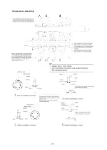
Page 51: ... 48 Transmission Assembly ...

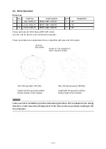
Page 52: ...arts are for 520 chains STD 525 chain Use the nuts for the kit to mount the drive sprocket These sprockets are manufactured to be compatible with new and old models NOTICE Take care not to install the sprocket in the wrong direction If it is installed in the wrong direction it will cause the misalignment of the drive and rear sprockets leading to the loss of power ...

Page 53: ... 50 Parts List No PART No PART NAME Q TY REMARKS 1 90179 20005 NUT SPROCKET 1 2 90215 21256 WASHER TONGUED 1 NOTICE When using this sprocket nut also use the drive sprocket nut of the kit ...

Page 54: ...2C0 15580 00 STARTER CLUTCH OUT ASSY 1 4 2C0 15536 00 CLIP STARTER 1 5 2C0 15411 71 COVER CRANKCASE 1 1 6 90149 06080 SCREW 3 With screw lock 7 2C0 15451 70 GSKT CRANKCASE COVER 1 1 ANTI STICK TYPE TIP Regarding Assembly 1 Remove grease from the taper surfaces of both rotor and crank before assembling them 2 ...

Page 55: ...COMP 1 2 90450 25037 HOSE CLAMP ASSY 4 3 13S 15373 70 PIPE BREATHER 1 4 2C0 15393 70 PIPE BREATHER 2 1 5 2C0 2419F 00 BRKT 1 6 91317 06020 BOLT HEX SOCKET HEAD 2 7 90480 13018 GROMMET 2 8 90119 06044 BOLT HEX W WASHER 2 9 2C0 15373 70 PIPE BREATHER 1 For 2006 and 2007 models ...

Page 56: ...The spring rate of the standard rear suspension is 103 N mm The free length is 152 9 mm for STD KIT springs R6180501Rev No PART No PART NAME Q TY REMARKS 1 BN6 22222 75 SPRG Rr SHOCK 1 108 N mm Identifying stamp 152 9 56 108 2 BN6 22222 80 SPRG Rr SHOCK 1 113 N mm Identifying stamp 152 9 56 113 3 BN6 22222 85 SPRG Rr SHOCK 1 118 N mm Identifying stamp 152 9 56 118 R6EN181106Rev ...

Page 57: ...s 2 There are slits at the ends of the spring for The number of slits indicates the rate as shown above These springs are only for the standard fork of BN6 17 18 models Free length is 219 5 mm for both STD KIT springs For spring replacement method BN6 STD Please refer to service manual The spring rate of STD is 9 0 N mm R6180501Rev TIP Use Yamaha M1 suspension oil ...

Page 58: ... 55 References ...

Page 59: ... 56 Parts List No PART No PART NAME Q TY REMARKS 1 13S 24713 70 CUSHION SEAT 1 Anti slip seat Cut to any size for use ...

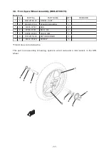
Page 60: ...aring spacers an air valve and a rotor sensor in the STD wheel No PART No PART NAME Q TY REMARKS 1 B60 25168 00 WHEEL CAST 1 2 B60 25117 00 SPACER BEARING 1 3 93306 00507 BRG 2 4 93106 31001 SEAL OIL 2 5 93900 00030 VALVE RIM 1 6 1SD 2517G 00 ROTOR SENSOR 1 7 90149 05029 SCREW 5 ...

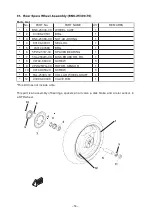
Page 61: ...ART No PART NAME Q TY REMARKS 1 BN6 25338 00 WHEEL CAST 1 2 93306 20531 BRG 1 3 BN6 2538E 00 NUT ADJUSTING 1 4 93106 40001 SEAL OIL 1 5 93317 43580 BRG 1 6 5PW 25317 00 SPACER BEARING 1 7 5SL 2582W 00 DISK BRAKE RR RH 1 8 90149 08009 SCREW 5 9 2PW 2517G 00 ROTOR SENSOR 1 10 90149 05029 SCREW 5 11 5SL 25383 00 COLLAR WHEEL SHAFT 1 12 93900 00030 VALVE RIM 1 ...

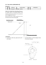
Page 62: ... throttle is fully opened is 57 5 as against STD 64 4 Except this part all other parts such as a throttle wire should be STD parts Installation 1 Replace the STD tube guide with the KIT tube guide the pull side cap grip No PART No PART NAME Q TY REMARKS 1 2CR 26243 70 TUBE GUIDE 1 ...

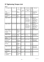
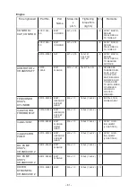
Page 63: ...READ AND BEARING SUR FACE SEE page 69 FOR DETAILS Tighten HEAD on side of CAM CHAIN compartment 90110 06094 BOLT HEXAGON SOCKET HEAD M6 x 1 0 12 0 2 1 2 0 2 2 WITH WASHER SPARK PLUG 5FL 1119C 70 13S 1119C 70 PLUG SPARK M10S x 1 0 12 15 1 2 1 5 4 SEE page 22 FOR DETAILS HEAD COVER x HEAD 90109 066F0 BOLT M6 x 1 0 10 0 2 1 0 0 2 6 Plug for sand drain hole 90340 18002 PLUG STRAIGHT SCREW M18 x 1 5 42...

Page 64: ...NG SURFACE AND THREAD AND TO BOTH SIDES OF WASHER USE MORI COATED WASHER TENSIONER ASSY x CYLINDER 90110 06106 BOLT HEXAGON SOCKET HEAD M6 x 1 0 12 0 2 1 2 0 2 2 INSTALL TEN SIONER ASSY Install COVER THERMOSTAT 91312 06020 BOLT HEXAGON SOCKET HEAD M6 x 1 0 12 0 2 1 2 0 2 2 Install JOINT 90105 06082 BOLT FLANGE SMALL HEAD M6 x 1 0 10 0 2 1 0 0 2 2 APPLY LOCK ING AGENT LOCKTITE Install WATER PUMP 90...

Page 65: ...LOCK ING AGENT LOCKTITE OIL COOLER x CARNKCASE 2 5EB 12822 00 BOLT UNION M20 x 1 5 63 0 3 6 3 0 3 1 APPLY OIL TO THREAD AND BEARING SUR FACE UPPER CASE x CAP CASE ASSY 92012 06020 BOLT BUTTON HEAD M6 x 1 0 5 0 0 5 0 5 0 05 4 UPPER CASE x LOWER CASE 98902 05020 SCREW CROSS RECESS BINDING M5 x 0 8 2 0 0 5 0 2 0 05 10 ELEMENT x UPPER CASE 98902 05020 SCREW CROSS RECESS BINDING M5 x 0 8 2 0 0 5 0 2 0 ...

Page 66: ...BN6 1133E 00 BN6 1133F 00 WIRE PULLEY 1 WIRE PULLEY 2 M6 x 1 0 5 7 0 5 0 7 2 2 Install MUFFLER PROTECTOR 90111 06071 BOLT HEXAGON SOCKET BUTTON M6 x 1 0 8 0 1 5 0 8 0 15 1 APPLY LOCK ING AGENT LOCKTITE Install MUFFLER PROTECTOR 90111 06099 BOLT HEXAGON SOCKET BUTTON M6 x 1 0 6 5 1 5 0 65 0 15 2 APPLY LOCK ING AGENT LOCKTITE EXHAUST VALVE SUB ASSY 90179 06063 NUT M6 x 1 0 6 5 1 5 0 65 0 15 1 CRANKC...

Page 67: ...G SURFACE CRANKCASE 1 x CRANKCASE 2 95812 06030 BOLT FLANGE M6 x 1 0 10 0 2 1 0 0 2 1 APPLY OIL BOTH TO THREAD AND TO BEARING SURFACE Install COVER CRANKCASE 1 90110 06387 BOLT M6 x 1 0 12 0 2 1 2 0 2 7 nstall COVER CRANKCASE 1 90110 06390 BOLT M6 x 1 0 12 0 2 1 2 0 2 2 APPLY LOCK ING AGENT LOCKTITE Install COVER CRANKCASE 2 90110 06388 BOLT M6 x 1 0 12 0 2 1 2 0 2 7 Install COVER CRANKCASE 2 9011...

Page 68: ...NOT TO OVER TIGHTEN COVER CRANKCASE 1 x CLAMP 90149 06082 SCREW M6 x 1 0 10 0 2 1 0 0 2 1 STATOR LEAD APPLY LOCK ING AGENT LOCKTITE Install COVER 90109 06387 BOLT M6 x 1 0 12 0 2 1 2 0 2 5 Install OIL PIPE OUTSIDE 90110 06161 BOLT HEXAGON SOCKET HEAD M6 x 1 0 12 0 2 1 2 0 2 2 APPLY LOCK ING AGENT LOCKTITE CRANKCASE 2 x PICKUP 90110 06168 BOLT HEXAGON SOCKET HEAD M6 x 1 0 10 0 2 1 0 0 2 2 APPLY LOC...

Page 69: ...tall ROTOR PICKUP 90105 08113 BOLT FLANGE M8 x 1 25 35 0 5 3 5 0 5 1 Install STARTER MOTOR 90105 06083 BOLT FLANGE SMALL HEAD M6 x 1 0 10 0 2 1 0 0 2 2 NEUTRAL SWITCH ASSY 3GB 82540 01 NEUTRAL S W ASSY M10 x 1 25 17 0 2 1 7 0 2 1 OVERTIGHTEN ING LEADS TO DAMAGE Install OIL LEVEL SENSOR 95022 06016 BOLT FLANGE SMALL HEAD M6 x 1 0 10 0 2 1 0 0 2 2 APPLY GREASE TO O RING CAM SENSOR x COVER H C 90110 ...

Page 70: ... 20 25 2 0 2 5 4 E G BRACKET FRONT 95024 10040 BOLT FLANGE SMALL HEAD M10 x 1 25 35 45 3 6 4 6 4 E G BRACKET REAR UPPER 90105 12228 BOLT FLANGE M12 x 1 25 1 90179 12004 NUT M12 x 1 25 58 70 5 9 7 1 1 E G BRACKET REAR UNDER 90105 12228 BOLT FLANGE M12 x 1 25 1 90179 12004 NUT M12 x 1 25 58 70 5 9 7 1 1 MAIN FRAME REAR FRAME 90149 10002 SCREW M10 x 1 25 33 40 3 3 4 1 4 PIVOT SHAFT FRAME 2C0 22141 10...

Page 71: ...5 4 FRONT STAY for FUEL TANK FRAME 90110 06233 BOLT HEXAGON SOCKET HEAD M6 x 1 0 3 5 0 3 0 5 1 Mid portion of FUEL TANK STAY 90119 06262 BOLT HEXAGON WITH WASHER M6 x 1 0 7 10 0 7 1 0 2 BRACKET TANK rear FUEL TANK 95812 06090 BOLT FLANGE M6 x 1 0 3 5 0 3 0 5 1 95702 06500 NUT FLANGE M6 x 1 0 1 FRONT WHEEL SHAFT FR FORK 90179 24004 NUT M24 x1 0 100 130 10 13 1 REAR WHEEL SHAFT NUT 90185 24008 NUT S...

Page 72: ...m 2 5 kgf m and tighten 8 and 9 to a torque of 30 N m 3 1 kgf m 2 Next in sequence tighten 1 to 7 and 10 to a torque of 42 N m 4 2 kgf m and tighten 8 and 9 to a torque of 60 0 N m 6 1 kgf m TIP The numbers 1 to 10 show the sequence in which the bolts are tightened Apply engine oil to the bolt threads contact surfaces and washers ...

Page 73: ...f 50 5 4 Retighten the bolts in the tightening sequence of 8 and 9 to a turn of nut angle of 75 5 5 Retighten the bolt in the sequence of 10 to a turn of nut angle of 50 5 6 Tighten the bolts in the tightening sequence of 11 and 12 to 24 2 N m 2 4 0 2 kgf m 7 Tighten the bolts in the tightening sequence of 13 to 29 to 10 2 N m 1 0 0 2 kgf m TIP The numbers 1 to 29 show the sequence in which the bo...

Page 74: ...ENSOR NSOR Pb NSOR Pa SOR SOR SENSOR ENSOR TOR SENSOR ...

Page 75: ......

Page 76: ...Published by YAMAHA MOTOR ENGINEERING co LTD ...

Reviews: