background image

46

Setting the manufacturer code

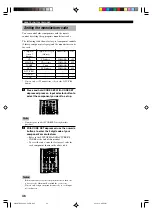
You can control other components with the remote
control by setting the appropriate manufacturer code.

The following table shows factory-set component controls
(Library: component category) and the manufacturer code
for each.

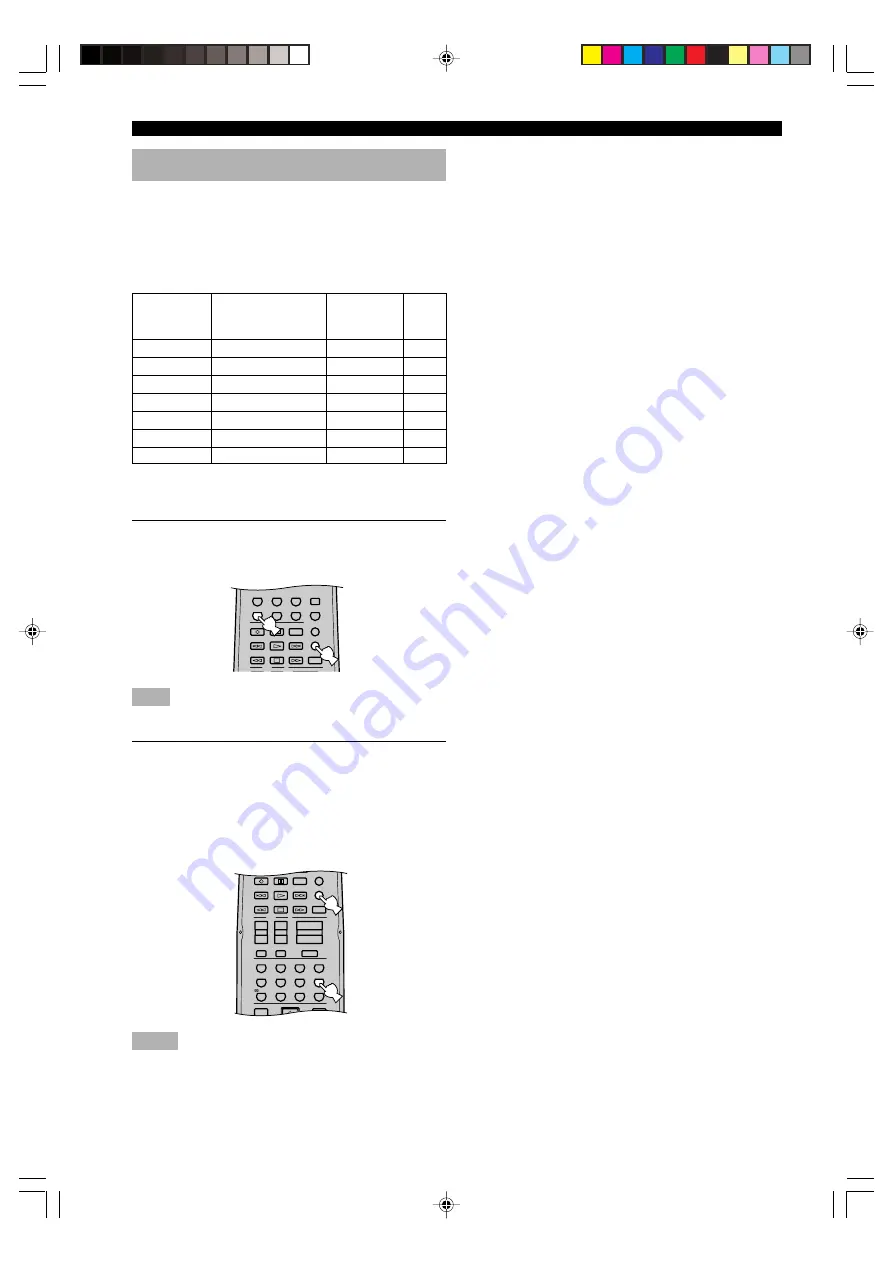
1

Press and hold CODE SET. With CODE SET
depressed, press an input selector button to
select the component you want to set up.

Note

• You must press and hold CODE SET throughout this

procedure.

2

With CODE SET depressed, use the numeric
buttons to enter the 3 digit code of your
component’s manufacturer.

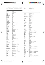
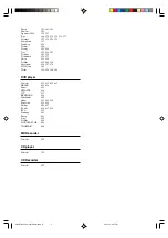
• Refer to the LIST OF MANUFACTURER’S

CODES at the end of this manual.

• To reset the code, enter the factory-set code for

each component shown in the above table.

Notes

• If the manufacturer of your component has more than one

code, try each of them until you find the correct one.

• You can only assign one manufacturer code to each input

selector button.

Component

control

(buttons)

CD

MD/CD-R

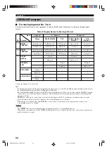
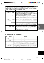
TUNER

DVD

D-TV/CBL*

V-AUX

VCR

Component category

(Library)

CD player

CD recorder

Tuner

DVD player

Manufacturer

YAMAHA

YAMAHA

YAMAHA

YAMAHA

Code

199

499

699

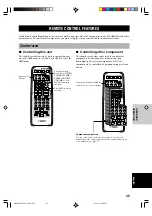
REMOTE CONTROL FEATURES

ENTER

+10

0

9

STEREO

 /DTS

8

7

6

5

4

3

2

1

ENTERTAINMENT

ROCK

JAZZ

HALL

TV

AMP

CODE SET

MUTE

INPUT

MUTE

REC

6CH INPUT

AUDIO

DISC SKIP

VOLUME

+

+

+

CH

VOL

SET MENU

LEVEL

MENU

TITLE

MATRIX 6.1

SELECT

-

1 - MOVIE THTR - 2

MONO MOVIE

TV SPORTS

V-AUX

VCR

D-TV/CBL

DVD

SLEEP

TUNER

MD/CD-R

CD

TV

AMP

CODE SET

REC

6CH INPUT

AUDIO

DISC SKIP

* You can only set TV manufactur codes for the D-TV/CBL

buttons.

0109HTR5635_45-50_EN.p65

02.12.12, 6:55 PM

46

Summary of Contents for HTR-5635

Page 1: ...OWNER S MANUAL HTR 5635 U AV Receiver 0100HTR5635_cv14 p65 02 12 12 7 05 PM 3 ...

Page 2: ...ave been adhered to 11 Power Sources This product should be operated only from the type of power source indicated on the marking label If you are not sure of the type of power supply to your home consult your product dealer or local power company For products intended to operate from battery power or other sources refer to the operating instructions 12 Grounding or Polarization This product may be...

Page 3: ...te retailer please contactYamaha Electronics Corp U S A 6660 Orangethorpe Ave Buena Park CA 90620 The above statements apply ONLY to those products distributed by Yamaha Corporation of America or its subsidiaries FCC INFORMATION for US customers only Note to CATV system installer This reminder is provided to call the CATV system installer s attention to Article 820 40 of the NEC that provides guid...

Page 4: ...ge to this unit and or personal injury YAMAHA will not be held responsible for any damage resulting from use of this unit with a voltage other than specified CAUTION READ THIS BEFORE OPERATING YOUR UNIT 13 To prevent damage by lightning disconnect the power cord from the wall outlet during an electrical storm 14 Do not attempt to modify or fix this unit Contact qualifiedYAMAHA service personnel wh...

Page 5: ...9 ADJUSTING THE PARAMETER SETTINGS FOR PRO LOGIC II MUSIC 50 Changing parameter settings 50 PRO LOGIC II Music parameter descriptions 50 PREPARATION SPEAKER SETUP 9 Speakers 9 Speaker placement 9 Connecting the speakers 10 CONNECTIONS 13 Before connecting components 13 Connecting video components 14 Connecting audio components 16 Connecting the antennas 17 Connecting an external decoder 18 Connect...

Page 6: ... A converter SET MENU for optimizing this unit for your Audio Video system Test tone generator for easier speaker balance adjustment 6 channel external decoder input Optical and coaxial digital audio signal jacks Sleep timer Remote control with preset manufacturer codes About this manual y indicates a tip for your operation Some operations can be performed by using either the buttons on the main u...

Page 7: ...e and manganese batteries together Read the packaging carefully as these different types of batteries may have the same shape and color If the batteries have leaked dispose of them immediately Avoid touching the leaked material or letting it come into contact with clothing etc Clean the battery compartment thoroughly before installing new batteries AM loop antenna Indoor FM antenna Batteries 2 AA ...

Page 8: ...he output level of all audio channels This does not affect the OUT REC level 7 6CH INPUT Selects the audio source connected to the 6CH INPUT jacks This audio takes priority over the source selected with INPUT l h or the input selector buttons on the remote control 8 SILENT PHONES jack Allows you enjoy DSP effect for private listening with headphones When you connect headphones no signals are outpu...

Page 9: ...he assignment of two preset stations with each other t PRESET TUNING l h Selects preset station numbers 1 to 8 when the colon appears in the front panel display Selects the tuning frequency when the colon does not appear y A B C D E Selects preset station groups A to E u BASS Adjusts the low frequency response for the main left and right channels Turn right to increase or turn left to decrease the...

Page 10: ...e audio output to the previous volume level r STEREO Switches between normal stereo and DSP effect reproduction When STEREO is selected 2 channel signals are directed to the main left and right speakers without effect sounds and all Dolby Digital and DTS signals except the LFE channel are mixed down to the main left and right speakers t SET MENU Selects the SET MENU mode CONTROLS AND FUNCTIONS Thi...

Page 11: ...ces or in places subject to extremely low temperatures CONTROLS AND FUNCTIONS NATURAL SOUND AV RECEIVER SILENT PHONES STEREO EFFECT PROGRAM PRESET TUNING A B C D E BASS TREBLE INPUT INPUT M0DE 6CH INPUT VOLUME STANDBY ON MEMORY FM AM EDIT PRESET TUNING MAN L AUTO FM AUTO MAN L MONO TUNING MODE 30 30 SYSTEM POWER STANDBY POWER AV POWER TV POWER TV ENTER 10 0 9 STEREO MATRIX 6 1 SELECT DTS 8 7 6 5 1...

Page 12: ...lti information display Shows the current DSP program name and other information when adjusting or changing settings 0 STEREO indicator Lights up when this unit is receiving a strong signal for an FM stereo broadcast while the AUTO indicator is lit q TUNED indicator Lights up when this unit is tuned to a station w MEMORY indicator Flashes to show a station can be stored e AUTO indicator Shows that...

Page 13: ...ffect channel with high fidelity when playing back Dolby Digital or DTS signals The YAMAHA Active Servo Processing Subwoofer System is ideal for natural and lively bass reproduction Speaker placement Refer to the following diagram when you place the speakers Main speakers Place the main left and right speakers an equal distance from the ideal listening position The distance between each speaker an...

Page 14: ...itive Black negative SPEAKER SETUP A speaker cord is actually a pair of insulated cables running side by side One cable is colored or shaped differently perhaps with a stripe groove or ridge 1 Remove approximately 10 mm 3 8 of insulation from each of the speaker cables 2 Twist the exposed wires of the cable together to prevent short circuits Connecting to the SPEAKERS terminals 1 Open the tab 2 In...

Page 15: ...ding theYAMAHA Active Servo Processing Subwoofer System connect the input jack of the subwoofer system to this jack Low bass signals distributed from the main center and or rear channels are directed to this jack in accordance with your SPEAKER SET selections The LFE low frequency effect signals generated when Dolby Digital or DTS is decoded are also directed to this jack in accordance with your S...

Page 16: ...r The impedance must be 8 Ω or higher The impedance of each speaker must be 8 Ω or higher IMPEDANCE SELECTOR switch WARNING Do not change setting of the IMPEDANCE SELECTOR switch when the power of this unit is on this may damage the unit If this unit fails to turn on when STANDBY ON or SYSTEM POWER is pressed the IMPEDANCE SELECTOR switch may not be fully slid to either position If so slide the sw...

Page 17: ...for direct transmission of digital signals through either coaxial or fiber optic cables You can use the digital jacks to input PCM Dolby Digital and DTS bitstreams To enjoy multi channel sound track of DVD software etc with DSP effect you need to make digital connection All digital input jacks are acceptable for 96 kHz sampling digital signals Note The OPTICAL jacks on this unit conform to the EIA...

Page 18: ... video component to the AUDIO jacks on this unit Connecting another video component Connect the audio signal output jacks on your video component to the AUDIO jacks and connect the video signal output jack on the component to the VIDEO jack on this unit Connecting a VCR or DVR digital video recorder Connect the audio signal input jacks on your video component to the AUDIO OUT jacks and connect the...

Page 19: ... L R L R VIDEO INPUT V VIDEO OUTPUT O OPTICAL OUTPUT V AUDIO INPUT VIDEO OUTPUT VIDEO INPUT L R L R V V AUDIO OUTPUT VIDEO OUTPUT AUDIO OUTPUT L R V AUDIO OUTPUT VIDEO OUTPUT L R V O V L R indicates video cables indicates optical cables indicates right analog cables indicates left analog cables indicates signal direction Video monitor VCR DVD player TV digital TV cable TV Another video component C...

Page 20: ... recording component Note Once you have connected a recording component to this unit keep its power turned on while using this unit If the power is off this unit may distort the sound from other components L R DIGITAL INPUT 6CH INPUT AUDIO TUNER AM ANT FM ANT GND 75Ω UNBAL VIDEO VIDEO VIDEO CD COAXIAL OPTICAL DVD DVD VCR IN OUT D TV CBL MD CD R IN PLAY CD V AUX SUB WOOFER SUB WOOFER MONITOR OUT SU...

Page 21: ...erience poor reception quality an outdoor antenna may improve the quality Consult the nearest authorized YAMAHA dealer or service center about the outdoor antennas TUNER AM ANT FM ANT GND 75Ω UNBAL EO VIDEO VIDEO Ground GND terminal For maximum safety and minimum interference connect the antenna GND terminal to a good earth ground A good earth ground is a metal stake driven into moist earth Indoor...

Page 22: ...field processor and you cannot listen to DSP programs When you select 6CH INPUT as the input source settings of 1 SPEAKER SET on the SET MENU do not apply except for 1E MAIN Lv Connecting the power supply cords Connecting the AC power cord Plug in this unit to the wall outlet AC OUTLETS SWITCHED U S A and Canada models 2 OUTLETS Use these outlets to connect the power cords from your components to ...

Page 23: ...ed to this unit if you want to play material from a video source NATURAL SOUND AV RECEIVER SILENT PHONES STEREO EFFECT PROGRAM PRESET TUNING A B C D E BASS TREBLE INPUT INPUT M0DE 6CH INPUT VOLUME STANDBY ON MEMORY FM AM EDIT PRESET TUNING MAN L AUTO FM AUTO MAN L MONO TUNING MODE 1 STANDBY ON or Remote control Front panel SYSTEM POWER STANDBY POWER AV POWER TV POWER TV V AUX VCR D TV CBL DVD SLEE...

Page 24: ...MAIN BOTH Nrm Normal 10 dB SPEAKER MODE SETTINGS This unit has 5 SPEAKER SET items on the SET MENU that you must set according to the number of speakers in your configuration and their size The following table summarizes these SPEAKER SET items and shows the initial settings as well as other possible settings If the initial settings shown in the following table are not appropriate for your speaker...

Page 25: ...ASS TREBLE INPUT INPUT M0DE 6CH INPUT VOLUME STANDBY ON MEMORY FM AM EDIT PRESET TUNING MAN L AUTO FM AUTO MAN L MONO TUNING MODE 2 2 VOLUME Remote control Front panel or Subwoofer test tone is output after the rear left speaker LEFT SURROUND The front panel display shows which speaker is outputting the test tone Note If the test tone cannot be heard turn down the volume set this unit to standby m...

Page 26: ...rear right and left speakers If 1D BASS on the SET MENU is set to MAIN the test tone will be circulated skipping the subwoofer y It is not necessary to readjust the speaker levels once they are set as long as you do not change the speakers You can enjoy listening to or watching the input source at the desired volume simply by adjusting the VOLUME knob or VOLUME on the remote control If the output ...

Page 27: ...ect another input source first press 6CH INPUT to turn off 6CH INPUT from the front panel display INPUT L R VOLUME VCR V AUX DVD TUNER CD D TV CBL MD CD R NATURAL SOUND AV RECEIVER SILENT PHONES STEREO EFFECT PROGRAM PRESET TUNING A B C D E BASS TREBLE INPUT INPUT M0DE 6CH INPUT VOLUME STANDBY ON MEMORY FM AM EDIT PRESET TUNING MAN L AUTO FM AUTO MAN L MONO TUNING MODE 1 3 5 3 5 6 STANDBY ON POWER...

Page 28: ...played digitally Example 70 0 dB Control range VOLUME MUTE minimum to 0 dB maximum The volume level indicator also shows the current volume level as a bar graph If desired use BASS and TREBLE These controls only effect the sound from the main speakers Notes If you increase or decrease the high frequency or the low frequency sound to an extreme level the tonal quality from the center and rear speak...

Page 29: ... can handle 96 kHz sampling digital signals Note the following when 96 kHz sampling digital signal is input to this unit DSP programs cannot be selected Sound will be output as 2 channel stereo from only the main left and right speakers There may be sound output from the subwoofer depending on the SPEAKER MODE settings on the SET MENU Therefore the level of the effect speakers cannot be adjusted w...

Page 30: ...ker If 1A CENTER on the SET MENU is set to NON the center channel sound is output from the main speakers y You can also select DSP program by pressing PROGRAM l h on the front panel Select a program based on your listening preference Program names are just for reference Selecting a sound field program You can enhance your listening experience by selecting a DSP program For details about each progr...

Page 31: ...OLUME VCR V AUX DVD TUNER CD D TV CBL MD CD R Remote control NATURAL SOUND AV RECEIVER SILENT PHONES STEREO EFFECT PROGRAM PRESET TUNING A B C D E BASS TREBLE INPUT INPUT M0DE 6CH INPUT VOLUME STANDBY ON MEMORY FM AM EDIT PRESET TUNING MAN L AUTO FM AUTO MAN L MONO TUNING MODE PROGRAM l h ENTER 10 0 9 STEREO DTS 8 7 6 5 4 3 2 1 ENTERTAINMENT ROCK JAZZ HALL MUTE SET MENU SELECT PRESET CH A B C D E ...

Page 32: ...lby Digital Surround EX or DTS ES software Press MATRIX 6 1 to turn on the Dolby Digital Matrix 6 1 or DTS Matrix 6 1 decoder The display changes AUTO Matrix6 1 OFF each time the MATRIX 6 1 button is pressed AUTO This mode automatically switches Dolby Digital Matrix 6 1 and DTS Matrix 6 1 depending on the signal Virtual rear center speaker does not work for 5 1 channel sources Matrix6 1 This setti...

Page 33: ...y time of the signals output from the three effect speakers to localize the virtual sound sources and fully encompass the listener Hi Fi DSP programs The following list gives you a brief description of the sound fields produced by each of the DSP programs Keep in mind that most of these are precise digital recreations of actual acoustic environments No 1 2 3 4 Program CONCERT HALL JAZZ CLUB ROCK C...

Page 34: ...ner can enjoy realistic dialogue depth of sound smooth transition between sound sources and a surround sound field that goes beyond the screen When a DTS or Dolby Digital signal is detected the CINEMA DSP sound field processor automatically chooses the most suitable sound field program for that signal L SURROUND SOUND FIELD R SURROUND SOUND FIELD PRESENCE SOUND FIELD DIALOG EFFECT MUSIC In additio...

Page 35: ...out sacrificing the clear separation of all channels Dolby Digital DTS Matrix 6 1 DSP sound field effect These programs provide you with the maximum experience of the spacious surround effects by adding an extra rear center DSP sound field created from the virtual rear center speaker Dolby Pro Logic DSP sound field effect Most movie software has 4 channel left center right and surround sound infor...

Page 36: ...gram will automatically switch to the Dolby Digital playback sound field or DTS playback sound field If Dolby Digital Surround EX software or DTS ES software is played when AUTO is selected by pressing the MATRIX 6 1 button on the remote control the Dolby Digital Matrix 6 1 or DTS Matrix 6 1 decoder usually turns on and the corresponding DSP program is selected MATRIX 6 1 on the remote control can...

Page 37: ... incredibly real This is ideal for any kind of video source encoded with Dolby Surround Dolby Digital or DTS especially large scale movie productions This program clearly reproduces dialog and sound effects in the latest sound form of science fiction films thus creating a broad and expansive cinematic space amid the silence You can enjoy science fiction films in a virtual space sound field that in...

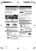
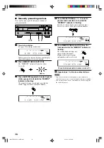
Page 38: ...e signal quality Automatic and manual tuning There are 2 ways to tune automatic and manual Automatic tuning is effective when station signals are strong and there is no interference Automatic tuning 1 Press INPUT l h TUNER on the remote control to select TUNER as the input source 2 Press FM AM to select the reception band FM or AM appears on the front panel display 3 Press TUNING MODE AUTO MAN L M...

Page 39: ...er that preset number When a station data is stored under a preset number the frequency and reception band are also stored You can manually replace a preset station with another FM or AM station by simply following the procedure in the section Manually presetting stations on page 36 If the number of the received stations does not reach E8 automatic preset tuning has automatically stopped after sea...

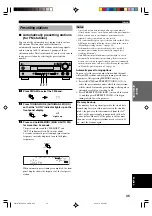
Page 40: ...n the front panel display shows the frequency of received station 2 Press MEMORY MAN L AUTO FM The MEMORY indicator flashes for about 5 seconds 3 Press A B C D E repeatedly to select a preset station group A to E while the MEMORY indicator is flashing The group letter appears and make sure that the colon appears on the front panel display MEMORY MAN L AUTO FM MEMORY A B C D E C AM 63O kHz L R TUNE...

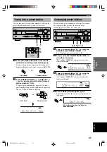
Page 41: ...d on the remote control to select a preset station number 1 to 8 The preset group and number appear on the front panel display along with the station band frequency and the TUNED indicator lights up EDIT PRESET TUNING PRESET TUNING A B C D E A5 FM 9O 6 MHz L R TUNED MEMORY VOLUME VCR V AUX DVD TUNER CD D TV CBL MD CD R EDIT E1 A5 MEMORY VCR V AUX DVD TUNER CD D TV CBL MD CD R Shows the exchange of...

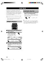
Page 42: ... AC OUTLET S The sleep timer can only be set with the remote control y By connecting a commercially available timer to this unit you can also set a wake up timer Refer to the operation instructions of the timer Setting the sleep timer 1 Select a source and start playback on the source component 2 Press SLEEP repeatedly to set the amount of time Each time you press SLEEP the front panel display cha...

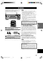
Page 43: ...mpting to digitally record the DTS bitstream will result in noise being recorded Therefore if you want to use this unit to record sources that have DTS signals recorded on them the following considerations and adjustments need to be made For LDs DVDs and CDs encoded with DTS when your player is compatible with the DTS format follow its operation instruction to make a setting so that the analog sig...

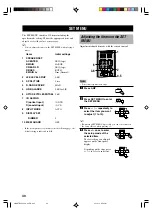
Page 44: ...just the items on the SET MENU while playing a source Items Initial settings 1 SPEAKER SET A CENTER LRG large B MAIN LARGE C REAR LR LRG large D BASS BOTH E MAIN Lv Nrm Normal 2 LFE LEVEL SP HP 0 dB 3 SP DLY TIME 0 ms 4 D RANGE SP HP MAX 5 L R BALANCE 0 dB for L R 6 HPTONE CTRL BASS TRBL 0 dB 7 I O ASSIGN C optical input 1 DVD D coaxial input 2 CD 8 INPUT MODE AUTO 9 DISPLAY SET DIMMER 0 10 MEM GU...

Page 45: ...g localization for several listeners and superior synchronization of sound and images Choices LRG large SML small NON none LRG Select this if you have a large center speaker The entire range of the center channel signal is directed to the center speaker SML Select this if you have a small center speaker The low frequency signals 90 Hz and below of the center channel are directed to the speakers se...

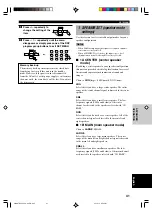
Page 46: ...fer Low frequency signals designated to the main channels in accordance with other speaker mode settings are directed to both main speakers and a subwoofer Note When you select MAIN for 1D BASS the low frequency signals 90 Hz and below of the main channel are directed to the main speakers even if you select SMALL for the main speaker mode 1E MAIN Lv main level mode Change this setting if you canno...

Page 47: ... of the center channel sounds y Increasing the delay by 1 ms simulates moving the speakers about 30 cm one feet farther away from the listening position Center speaker image 4 D RANGE dynamic range Use this feature to adjust the dynamic range This setting is effective only when this unit is decoding Dolby Digital signals SP D R SPEAKER HP D R HEADPHONE Choices MAX STD standard MIN minimum MAX Sele...

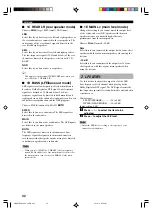
Page 48: ...onents Once you assign you can select that component with INPUT l h or the input selector buttons on the remote control 7C OPTICAL IN for OPTICAL INPUT jacks Choices 1 MD CD R CD V AUX VCR D TV CBL DVD 7D COAXIAL IN for COAXIAL INPUT jack Choices 2 MD CD R CD V AUX VCR D TV CBL DVD Notes You cannot select an item more than once for the same type of jack When you connect a component to both the COA...

Page 49: ...e selected components Select the component to be controlled by pressing an input selector button SYSTEM POWER STANDBY POWER AV POWER TV POWER TV ENTER 10 0 9 STEREO DTS 8 7 6 5 4 3 2 1 ENTERTAINMENT ROCK JAZZ HALL V AUX VCR D TV CBL DVD SLEEP TUNER MD CD R CD TV AMP CODE SET MUTE INPUT MUTE REC 6CH INPUT AUDIO DISC SKIP VOLUME CH VOL SET MENU SELECT PRESET CH A B C D E LEVEL MENU TEST RETURN DISPL...

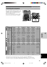
Page 50: ...or each component shown in the above table Notes If the manufacturer of your component has more than one code try each of them until you find the correct one You can only assign one manufacturer code to each input selector button Component control buttons CD MD CD R TUNER DVD D TV CBL V AUX VCR Component category Library CD player CD recorder Tuner DVD player Manufacturer YAMAHA YAMAHA YAMAHA YAMA...

Page 51: ... down 2 TV volume up 2 TV volume down 2 TV mute 2 TV input Numeric buttons VCR channel up VCR channel down Enter TV digital cableTV 3 VCR power 2 TV power 3 VCR rec 3 VCR play 3 VCR search backward 3 VCR search forward 3 VCR pause 3 VCR stop TV channel up TV channel down TV volume up TV volume down TV mute TV input Numeric buttons Enter CD player 1 Power 2 TV power Disc skip Play Search backward S...

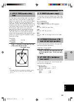
Page 52: ...ese speakers When you adjust the output level with LEVEL the settings you made with the test tone will be changed We recommend adjusting the speakers by following the steps described in Using the test tone on pages 21 and 22 For 5ch Stereo You can adjust the volume level for each channel in 5 channel stereo mode Control range 0 to 100 CT LEVEL Center level RL LEVEL Rear left level RR LEVEL Rear ri...

Page 53: ...t from the rear speakers The larger the value the later the sound effect is generated The delay time can be individually adjusted to all DSP programs The following table shows factory set delay time 1 2 3 4 5 6 7 8 9 Program CONCERT HALL JAZZ CLUB ROCK CONCERT DISCO GAME CONCERT VIDEO TV SPORTS MONO MOVIE 70 mm SPECTACLE DGTL SPECTACLE DTS SPECTACLE Spectacle 6 1 70 mm SCI FI Sci Fi 6 1 DGTL SCI F...

Page 54: ...on on extends the front stereo image to include the surround speakers for wraparound effect Choices OFF ON initial setting is OFF DIMENSION Function Gradually adjusts the soundfield either towards the front or towards the rear Control range 3 towards the rear to 3 towards the front initial setting is STD standard CT WIDTH Center width Function Adjusts the center image from all three front speakers...

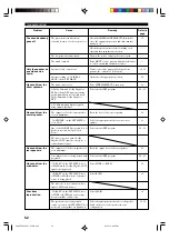
Page 55: ...ropriate input source has not been selected The speaker connections are not secure The volume is turned down The sound is muted Digital signals which this unit cannot reproduce are being input to this unit by playing a CD ROM etc Remedy Firmly connect the power cord Set the switch fully to the left or right position when this unit is in the standby mode Make sure all speaker wire connections on th...

Page 56: ...ayed 1D BASS on the SET MENU is set to SWFR or MAIN when a 2 channel source is being played The source does not contain low bass signals 90 Hz and below 1D BASS on the SET MENU is set to SWFR or BOTH and your system does not include a subwoofer The speaker mode settings main center or rear on the SET MENU does not match your speaker configuration Remedy Check the IMPEDANCE SELECTOR switch is set t...

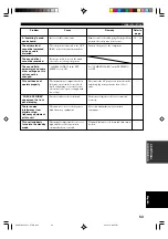
Page 57: ... is set to ON The internal microcomputer has been frozen by an external electric shock such as lightning or excessive static electricity or by a power supply with low voltage Speaker cables are short circuited This unit is too close to the digital or high frequency equipment The internal temperature becomes too high and the overheat protection circuitry has been activated Remedy Firmly connect the...

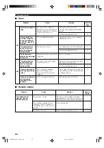
Page 58: ...emedy Check the antenna connections Try using a high quality directional FM antenna Use the manual tuning method Adjust the antenna position to eliminate multipath interference Use a high quality directional FM antenna Use the manual tuning method Re store the stations Tighten the AM loop antenna connections and orient it for best reception Use the manual tuning method Use an outdoor antenna and a...

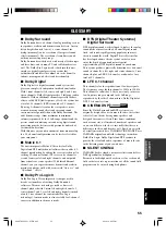
Page 59: ... II Dolby Pro Logic II is an improved technique used to decode vast numbers of existing Dolby Surround softwares This new technology enables a discrete 5 channel playback with 2 main left and right channels 1 center channel and 2 rear left and right channels instead of only 1 rear channel for conventional Pro Logic technology A music mode is also available for 2 channel sources in addition to the ...

Page 60: ...pulse code modulation the analog signal is encoded as pulses and then modulated for recording Sampling frequency and number of quantized bits When digitizing an analog audio signal the number of times the signal is sampled per second is called the sampling frequency while the degree of fineness when converting the sound level into a numeric value is called the number of quantized bits The range of...

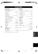
Page 61: ...PUT SUBWOOFER 4 0 V 1 2 kΩ VIDEO SECTION Video Signal Type NTSC or PAL Composite Video Signal Level 1 Vp p 75 Ω Signal to Noise Ratio 50 dB Frequency Response MONITOR OUT 5 Hz to 10 MHz 3 dB FM SECTION Tuning Range 87 5 to 107 9 MHz 50 dB Quieting Sensitivity IHF 100 mod Mono Stereo 2 0 µV 17 3 dBf 25 µV 39 2 dBf Selectivity 400 kHz 70 dB Signal to Noise Ratio IHF Mono Stereo 76 dB 70 dB Harmonic ...

Page 62: ...Sony 263 214 Sylvania 297 225 Telefunken 269 264 265 266 Thomson 223 266 Toshiba 292 226 267 215 Videch 297 242 Wards 297 239 232 VCR Yamaha 399 392 393 394 Admiral 395 Aiwa 396 397 398 329 Akai 322 323 324 Audio Dynamic 392 394 Bell Howell 393 Blaupunkt 325 326 Brocsonic 327 Bush 322 Canon 325 328 CGM 396 332 Citizen 396 Craig 396 Curtis Mathis 397 328 333 Daewoo 328 334 335 DBX 392 394 Dimensia ...

Page 63: ...5 369 389 Universum 396 327 376 W WHouse 396 Wards 395 396 336 362 DVD player Yamaha 699 622 623 647 DENON 623 624 Funai 625 HITACHI 626 JVC 627 KENWOOD 628 Mitsubishi 629 Onkyo 632 633 634 Panasonic 623 635 Philips 699 647 Pioneer 636 637 638 RCA 639 Samsung 642 Sharp 643 Sony 644 Toshiba 634 LG GOLD STAR 645 THOMSON 646 MD Recorder Yamaha 599 CD player Yamaha 199 CD Recorder Yamaha 499 0120HTR56...

Page 64: ...GERMANY YAMAHA ELECTRONIQUE FRANCE S A RUE AMBROISE CROIZAT BP70 CROISSY BEAUBOURG 77312 MARNE LA VALLEE CEDEX02 FRANCE YAMAHA ELECTRONICS UK LTD YAMAHA HOUSE 200 RICKMANSWORTH ROAD WATFORD HERTS WD1 7JS ENGLAND YAMAHA SCANDINAVIA A B J A WETTERGRENS GATA 1 BOX 30053 400 43 VÄSTRA FRÖLUNDA SWEDEN YAMAHA MUSIC AUSTRALIA PTY LTD 17 33 MARKET ST SOUTH MELBOURNE 3205 VIC AUSTRALIA Printed in Malaysia ...

Reviews: