background image

HTR-5920

3

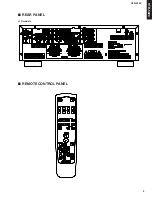
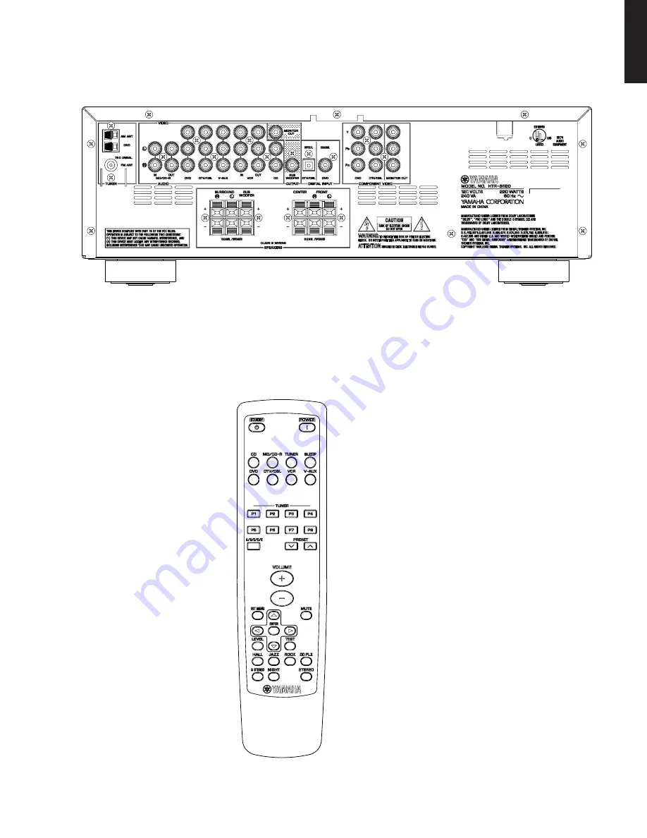
HTR-5920

REAR PANEL

U, C models

REMOTE CONTROL PANEL

Summary of Contents for HTR-5920

Page 1: ...YAMAHA products Modifications are therefore inevitable and specifications are subject to change without notice or obligation to retrofit Should any discrepancy appear to exist please contact the distributor s Service Division WARNING Static discharges can destroy expensive components Discharge any static electricity your body may have accumulated by grounding yourself to the ground buss in the uni...

Page 2: ...test for leakage with the AC plug in both polarities WARNING CHEMICAL CONTENT NOTICE The solder used in the production of this product contains LEAD In addition other electrical electronic and or plastic where applicable components may also contain traces of chemicals found by the California Health and Welfare Agency and possibly other entities to cause cancer and or birth defects or other reprodu...

Page 3: ...HTR 5920 3 HTR 5920 REAR PANEL U C models REMOTE CONTROL PANEL ...

Page 4: ...Ratio 50 dB or more Frequency Response Monitor out Composite 5 Hz to 10 MHz 3 dB Component 5 Hz to 60 MHz 3 dB FM Section Tuning Range 87 5 to 107 9 MHz 50dB Quieting Sensitivity IHF 100 mod Mono 30 dBf Signal to Noise Ratio IHF Mono stereo 73 dB 70 dB Harmonic Distortion 1 kHz Mono stereo 0 5 0 8 Antenna Input 75 ohms unbalanced AM Section Tuning Range 530 to 1 710 kHz Antenna Loop antenna Genera...

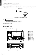
Page 5: ...ETTING THE SYSTEM Use this feature to reset all the parameters of this unit to the initial factory settings Note Be sure this unit is in standby mode This procedure completely resets all the parameters of this unit The initial factory settings are activated next time you turn on this unit 1 With this unit in standby mode hold down TONE CONTROL key on the front panel and press STANDBY ON key RESET ...

Page 6: ...4 5 6 7 8 9 0 A B Turn on the power while pressing these keys Keys of main unit INTERNAL VIEW FIRMWARE VERSION Microprocessor information To display the firmware version do the following procedure 1 Press the STANDBY ON key while simultaneously pressing those two keys of the main unit as indicated in the figure below 2 Numeric values in the figure example are for reference 3 Press STANDBY ON key 0...

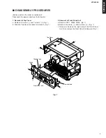
Page 7: ... Disconnect the power cable from the AC outlet 1 Removal of Top Cover a Remove 6 screws 1 and 7 screws 2 Fig 1 b Slide the Top Cover rearward to remove it Fig 1 2 Removal of Front Panel Unit a Remove CN11 CN83 CN96 Fig 1 b Remove 5 screws 3 and 5 screws 4 Fig 1 c Release a hook on the right side of the Front Panel Unit then remove the Front Panel Unit forward Fig 1 ...

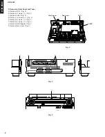
Page 8: ...Stopper Fig 3 Fig 4 3 Removal of Rear Panel and Tuner a Remove CN12 Fig 2 b Remove 2 screws 5 Fig 3 c Remove Tuner Fig 2 d Remove 15 screws 6 Fig 3 e Remove 2 screws 7 Fig 3 f Remove 6 screws 8 Fig 4 g Remove Cord Stopper Fig 2 h Remove Rear Panel Fig 2 Fig 2 ...

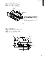
Page 9: ... careful not to bend the pin of the connectors CN13 and CN14 Heat Sink AMP 1 P C B CN95 CN93 CN91 CN90 B B A C 4 Removal of INPUT and AMP 4 P C B s a Remove 1 screw 9 and 2 screws 0 Fig 5 b Remove INPUT and AMP 4 P C B s Fig 5 Fig 5 5 Removal of AMP 1 P C B a Remove 2 screw A 5 screws B and 3 screw C Fig 6 b Remove CN90 CN91 CN93 and CN95 Fig 6 c Remove AMP 1 P C B with Heat Sink Fig 6 ...

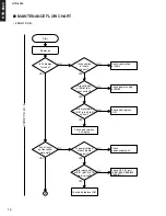
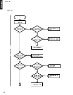
Page 10: ...BN82 pin 1 to 4 correct Check connection of cable NO NO NO NO Check power supply of BN82 Check and replace IC81 Check power supply part Check KEY IN part S851 854 S858 863 S865 871 Are waveforms of IC81 pin 34 to 67 correct Check and replace FL display Are input ports of IC81 pin76 to 78 work correct Check and replace IC81 Start Is power voltage of each board correct A FRONT P C B 1 3 FRONT P C B ...

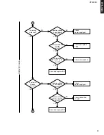
Page 11: ...y part Check and replace VR82 Check power supply part Check connection of cable Check circuit pattern Check and replace IC81 Is implementation of VR82 correct Is power voltage of each board correct A B Is power voltage of each board correct Are connections of CN96 and BN73 2 correct Check and replace JK81 YES YES YES YES YES YES YES FRONT P C B 2 3 ...

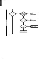
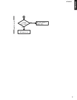
Page 12: ...veform of RC81 correct Check and replace IC81 Is power voltage of RC81 correct Is power voltage of each board correct FRONT P C B is O K NO NO NO Check power supply part Check power supply part Check and replace RC81 NO B YES YES YES YES FRONT P C B 3 3 ...

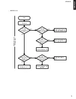
Page 13: ...ions for CN11 and FRONT board Check and replace IC21 Analog part is O K Check and replace IC21 NO NO NO YES YES YES YES YES Power on NO NO Check and replace IC81 and JK12 Start Are power voltages of IC22 and IC23 correct Are waveforms of IC21 pin 67 to 69 correct Are waveforms of IC21 pin 76 to 79 correct INPUT P C B 1 3 Analog part INPUT P C B ...

Page 14: ... and crystal oscillation part Are power voltage and oscillation of IC32 correct Are waveforms of IC31 pin 39 to 41 correct Are waveforms of IC32 pin 39 to 50 correct Are waveforms of IC31 pin 6 7 and 18 correct NO NO YES YES YES YES YES YES Power on NO NO Check and replace IC32 NO Check and replace IC32 NO Check and replace IC32 NO Check and replace IC32 Check analog part Start YES C D INPUT P C B...

Page 15: ...orrect when analog input Are waveforms of IC32 pin 51 and 52 correct Are power voltage and ground of IC32 correct Digital part is O K Check power supply part NO YES YES YES NO NO Check and replace IC32 C D INPUT P C B 3 3 Digital part ...

Page 16: ...eplace speaker relay RY62 64 Is implementation of speaker relay correct Are power voltages of IC91 to 93 correct Is input power voltage AC of D901 correct Is output power voltage DC of D901 correct Check connections of cable Check Front Board Check Power transformer NO NO YES YES YES YES Power on NO NO Check and replace D901 NO Check IC91 to 93 Start YES NO E AMP P C B 1 2 AMP P C B ...

Page 17: ...HTR 5920 17 HTR 5920 AMP P C B 2 2 NO YES Is output audio correct Check connections of speaker cable AMP board is O K E ...

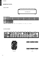
Page 18: ...n Pin No Connection Pin No 1 F 2 NX NX NX 3 NP 4 NP 5 1G2G 3G 4G 5G6G 7G 8G 9G 10G11G 6 7 8 9 10 11 12 13 14 15 16 17 18 P21 19 P20 20 P19 21 P18 22 P17 23 P16 24 P15 25 P14 26 P13 27 P12 28 P11 29 P10 30 P9 31 P8 32 P7 33 P6 36 P3 37 P2 38 P1 39 40 41 42 F NX NP NP 34 P5 35 P4 Connection HNA 11SM66T PIN CONNECTION GRID ASSIGNMENT PATTERN AREA 1 b a1 a2 d1 d2 b m c f h k r n j p g e ...

Page 19: ... p n c d1 d2 f a1 a2 h j k b m g e r p n c d1 d2 f a1 a2 h j k b m g e r p n c d1 d2 f a1 a2 h j k b m g e r p n c d1 d2 f a1 a2 h j k b m g e r p n c d1 d2 f a1 a2 h j k b m g e r p n c d1 d2 f a1 a2 h j k b m g e r p n c d1 d2 f a1 a2 h j k b m g e r p n c d1 d2 Dp f a1 a2 h j k b m s3 g e s1 s2 s4 r p n c d1 d2 P19 P20 P21 ANODE CONNECTION ...

Page 20: ...2 RESET XIN XOUT VSS INTS STOP P20 INT3 TC3 P30 TC4 P31 SCK P32 SI P33 SO P34 HSCK P35 P36 HSO P37 P66 G9 P65 G10 P64 G11 P63 G12 P62 G13 P61 G14 P60 G15 VDD P07 P06 P05 P04 P03 P02 P01 P00 VDD P9 VFT drive circuit automatic display Key scan control Program counter Register banks Stack Pointer P S W Interrupt Controller System Controller Standby Controller Timing Generator High frequ Low frequ Clo...

Page 21: ...INPUT OUTPUT OUTPUT OUTPUT OUTPUT OUTPUT INPUT INPUT OUTPUT INPUT OUTPUT OUTPUT INPUT INPUT OUTPUT OUTPUT OUTPUT OUTPUT OUTPUT INPUT OUTPUT OUTPUT OUTPUT OUTPUT OUTPUT OUTPUT OUTPUT INPUT INPUT INPUT INPUT INPUT INPUT INPUT INPUT INPUT INPUT INPUT INPUT OUTPUT SERIAL DATA SERIAL DATA SERIAL DATA SERIAL DATA SERIAL DATA SERIAL DATA SERIAL DATA SERIAL DATA LOW SERIAL DATA SERIAL DATA SERIAL DATA SER...

Page 22: ...R TR D Q 8 CL n p p CL D Q Q LATCH 8 TR CL S S CL CL TR 3 STATE 8 3 STATE 2 15 3 5 Q2 4 Q1 CLOCK OUTPUT ENABLE 11 Q8 Q Q 6 Q3 12 Q7 ALL INPUTS PROTECTED BY CMOS PROTECTION NETWORK 13 Q6 14 Q5 7 Q4 TR TR 1 STROBE LATCH 1 LATCH 2 3 STATE 1 10 11 n CL p p n n TR TR TR TR p VDD VSS n VDD 1 2 3 4 5 6 7 8 16 15 14 13 12 11 10 9 STROBE TOP VIEW DATA CLOCK Q1 Q2 Q3 Q4 VSS VDD OUTPUT ENABLE Q5 Q6 Q7 Q8 Q S...

Page 23: ... 1 16 8 1 9 1 BD3816K1 1 24 25 40 41 64 65 80 1 24 25 40 41 64 65 80 1N4003 UF4004 DQ10 1N4403S 1SS133 78L08 CS493264 BA4560RF 74LCX08 AK4589 TMP87PS71 74HCU04 LA7952 MC7805C HVIKIA7812API HVIKIA7912PI BVISTK402 120SE HYBRID ROHS CD4094 NJM2586 HVDMTZJ5 1BT HVDMTZJ4 7BT HVDMTZJ33BT HVDMTZJ4 3BT 1 2 3 ICs Diodes 1 OUT 2 COM 3 IN 1 15 Anode Cathode ...

Page 24: ...ors B C E E C B E C B E C B E B C E C B E C B KTD1304 2SC3200 KRA102MT 2SB811Y 2SC2785Y KTA1267YT KTA1268GRT KTD2058Y KTC3199YT KRC114MT KTC2874BT KTC3198Y 2SC2785 2SC2785Y 2SB811Y 2SA1271Y 2SC3199 2SA102M C E B KRC102MT BCE E C B ...

Page 25: ...74 75 78 79 76 77 48 23 24 57 IC32 IC31 PWR1 RY91 T901 RY61 RY61 RY62 RY63 RY64 RY63 59 51 52 20 22 24 1 4 9 6 8 2 3 5 12 13 2 4 3 10 15 MICROPROCESSOR INPUT FRONT AMP FRONT SPEAKERS FRONT L R SURROUND L R SUBWOOFER See page 31 32 SCHEMATIC DIAGRAM See page 34 SCHEMATIC DIAGRAM See page 34 SCHEMATIC DIAGRAM See page 33 SCHEMATIC DIAGRAM ...

Page 26: ...CIRCUIT BOARDS INPUT P C B Side A MONITOR OUT Y PB PR DVD Y PB PR DVD COAXIAL DTV CBL OPTICAL MONITOR OUT CD L R SUB WOOFER DVD V AUX DTV CBL OUT L R IN L R OUT L R IN L R L R L R L R DTV CBL Y PB PR COMPONENT VIDEO DIGITAL INPUT OUTPUT AUDIO VIDEO VCR MD CD R AMP 4 CN14 To tuner AMP 4 CN13 FRONT 1 CN81 Semiconductor Location ...

Page 27: ... I J 1 2 3 4 5 6 7 HTR 5920 27 IC18 F3 IC21 D4 IC24 E4 IC25 C5 IC26 D5 IC27 E5 IC28 C4 IC31 G5 IC32 F5 IC36 G6 IC37 G6 IC51 G4 Q143 E3 Q301 G6 Q302 F6 Q504 F4 Ref no Location INPUT P C B Side B Semiconductor Location ...

Page 28: ...G4 D702 G4 D703 H4 D704 H4 D705 H5 D706 G5 D931 C3 D932 B3 D933 B3 D934 B3 D935 A4 D936 B4 D937 B4 D938 C4 D939 B4 D950 C4 D951 C4 D952 C4 D953 C4 D954 C4 D955 C2 D956 C4 D957 C4 IC91 C6 Semiconductor Location Ref no Location Ref no Location IC92 E6 IC93 G6 IC94 H4 IC95 C3 IC96 D3 IC97 C4 IC98 B4 Q101 D4 Q102 D4 Q106 I5 Q107 I5 Q108 I5 Q109 I5 Q501 D6 Q502 A6 Q503 C5 Q504 B5 Q551 H4 Q552 H4 Q553 H...

Page 29: ...FRONT 1 BN82 AMP 1 BN93 AMP 2 P C B AMP 5 P C B AMP 6 P C B AMP 7 P C B AMP 3 P C B AMP 4 P C B AMP 1 CN94 AMP 1 CN92 INPUT BN14 INPUT BN13 Side A Side A Side A Side A Side A Side A Semiconductor Location D901 C3 D902 C3 D903 C3 D904 C3 D905 C3 D907 C3 D908 B3 D909 C3 D910 C3 Q915 B3 Ref no Location ...

Page 30: ...SET TUNING BASS TREBLE FRONT 1 BN73 STANDBY ON FRONT 3 BN73 2 FRONT 2 BN73 1 AMP 2 CN96 INPUT CN11 FRONT 1 P C B FRONT 2 P C B FRONT 3 P C B Side A Side A Side A Semiconductor Location D801 I4 D802 B3 D803 H3 D804 I4 D806 I4 D807 H2 D810 H2 D841 F6 D842 F6 D891 I4 D892 I4 IC81 E2 Q801 H2 Q802 H2 Q803 H4 Q805 I4 Q806 H2 Q808 G3 Ref no Location ...

Page 31: ... Recovery Clock Generator DAIF Decoder AC 3 MPEG Detect DEM P I F Audio I F X tal Oscillator PDN INT0 LRCK2 BICK2 SDTO2 DAUX2 MCKO2 XTO XTI R PVDD PVSS CDTI CDTO CCLK CSN DVDD DVSS TVDD MCKO1 I2C RX0 RX1 RX2 RX3 RX4 RX5 RX6 RX7 DIT TX0 Error Detect STATUS INT1 Q subcode buffer TX1 B C U VOUT 8 to 3 VIN Audio I F SCF SCF SCF SCF SCF SCF LOUT1 ROUT1 LOUT2 ROUT2 LOUT3 ROUT3 DAC DATT DEM ADC HPF ADC H...

Page 32: ...Y PB PR 10 35V 10 35V 10 35V 10 35V IC24 CD4094B 8 stage shift and store bus register 2 1 CL SERIAL IN SERIAL OUT SERIAL OUT CL CL CL D Q 2 STAGES 3 7 CL CL TR TR D Q 8 CL n p p CL D Q Q LATCH 8 TR CL S S CL CL TR 3 STATE 8 3 STATE 2 15 3 5 Q2 4 Q1 CLOCK OUTPUT ENABLE 11 Q8 Q Q 6 Q3 12 Q7 ALL INPUTS PROTECTED BY CMOS PROTECTION NETWORK 13 Q6 14 Q5 7 Q4 TR TR 1 STROBE LATCH 1 LATCH 2 3 STATE 1 10 1...

Page 33: ...e 34 H2 to AMP 3 _CN93 Page 33 F6 to AMP 1 _BN93 Page 33 H6 to FRONT 1 _BN82 Page 34 G4 To power transformer To thermistor POWER TRANSFORMER To power cable to AMP 1 _CN92 Page 33 B6 AMP 1 AMP 2 AMP 4 AMP 3 820P 820P 100 820P 820P 100 4 7K C3203Y 820P 820P IC94 CD4094B 8 stage shift and store bus register 2 1 CL SERIAL IN SERIAL OUT SERIAL OUT CL CL CL D Q 2 STAGES 3 7 CL CL TR TR D Q 8 CL n p p CL...

Page 34: ...P11 INT2 TC1 P12 DVO P13 P14 TC2 P15 P16 P17 TEST XTIN P21 XTIN P22 RESET XIN XOUT VSS INTS STOP P20 INT3 TC3 P30 TC4 P31 SCK P32 SI P33 SO P34 HSCK P35 P36 HSO P37 P66 G9 P65 G10 P64 G11 P63 G12 P62 G13 P61 G14 P60 G15 VDD P07 P06 P05 P04 P03 P02 P01 P00 VDD P9 VFT drive circuit automatic display Key scan control Program counter Register banks Stack Pointer P S W Interrupt Controller System Contr...

Page 35: ...ODE CHP CHIP DIODE DIODE VAR VARACTOR DIODE DIOD Z CHP CHIP ZENER DIODE DIODE ZENR ZENER DIODE DSCR CE CERAMIC DISCRIMINATOR FER BEAD FERRITE BEADS FER CORE FERRITE CORE FET CHP CHIP FET FL DSPLY FLUORESCENT DISPLAY FLTR CE CERAMIC FILTER FLTR COMB COMB FILTER MODULE FLTR LC RF LC FILTER EMI GND MTL GROUND PLATE GND TERM GROUND TERMINAL HOLDER FUS FUSE HOLDER IC PRTCT IC PROTECTOR JUMPER CN JUMPER...

Page 36: ...S7 S7 S7 S7 S7 S7 S7 S7 S3 S3 S3 S8 S12 S3 S3 P10 P11 P8 P7 P5 P6 S7 P5 P6 S7 S1 S5 S5 S5 S5 S1 S1 S2 S5 S5 P2 P1 P3 P4 S9 S10 S3 S3 S1 M3 C6 S1 P9 C7 S11 C5 C4 C3 3 C4 1 C4 6 C4 7 C2 2 C2 C1 3 C2 1 C4 5 C4 4 C4 2 S11 C8 S7 C9 M8 A1 A2 A3 Note The replacement battery cover is not available ...

Page 37: ...A13B100B M3 AAX76790 CABINET TOP CKC1A169G33 M8 AAX76830 PANEL REAR CKF1A305Z S1 AAX73490 BIND HEAD B TIGHT SCREW 3x6 MFZN2W3 CTB3 6J S2 AAX73500 BIND HEAD B TIGHT SCREW 3x8 MFC2 CTB3 8JFC S3 AAX74120 BIND HEAD B TIGHT SCREW 3x8 MFZN2W3 CTB3 8J S4 AAX73510 BIND HEAD B TIGHT SCREW 3x8 MFZN2BL CTB3 8JFZ S5 AAX73540 BIND HEAD P TIGHT SCREW 3x10 MFZN2Y CTB3 10G S6 AAX76800 BIND HEAD P TIGHT SCREW 3x10...

Page 38: ... 55 7A E5 7A E6 O O O O O O O O O O O O No Label Code Key 21 22 23 24 25 26 27 28 29 30 31 32 33 34 35 36 37 38 39 40 41 42 43 44 45 46 47 48 49 50 51 52 53 54 55 56 57 58 No Label Code Key No Label Code Key P3 P4 P5 P6 P7 P8 A B C D E PRESET PRESET VOL VOL SET MENU UP MUTE LEFT ENTER RIGHT LEVEL DOWN TEST HALL JAZZ ROCK Dolby PLII 5 STEREO NIGHT STEREO O O O O O O O O O O O O O O O O O O O O O O ...

Reviews: