RX-V359/HTR-5930
15
RX-V359/HTR-5930
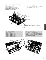
4. Removal of MAIN (1), DSP, FUNCTION (1),
FUNCTION (8) and FUNCTION (9) P.C.B.s
a. Remove 1 screw (
9
). (Fig. 4)
b. Remove CB803. (Fig. 4)
c. Remove FUNCTION (1) P.C.B. (Fig. 4)
d. Remove CB103, CB104 and CB652. (Fig. 4)
e. Remove 3 screws (
0
). (Fig. 4)
When checking the P.C.B.:
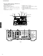
a. Remove the Top Cover.
b. Remove 4 screws (
7
). (Fig. 3)
c. Remove 3 screws (
0
). (Fig. 4)
d. Remove 4 screws (
A
). (Fig. 4)
e. Remove 1 screw (
B
). (Fig. 4)
Fig. A
Fig. 4
Fig. B
f. Remove 4 screws (
A
). (Fig. 4)
g. Remove MAIN (1), DSP, FUNCTION (4), FUNCTION
(8) and FUNCTION (9) P.C.B.s. (Fig. 4)
0
0
C
B
A
A
9
A
Note:
When assembling the FUNCTION (1) P.C.B., be careful not to
bend the pin of the connectors (CB101 and CB244).
FUNCTION (1) P.C.B.
DSP P.C.B.
FUNCTION (9) P.C.B.
FUNCTION (4) P.C.B.
FUNCTION (8) P.C.B.
CB104
CB103
CB652
CB803
MAIN (1) P.C.B.
Rear Panel
MAIN (1) P.C.B.
Ground lead
Ground lead
G241
G103
G104
Rear Panel
f. Remove 1 screw (
C
). (Fig. 4)
g. Place the P.C.B. upright. (Fig. A and B)
h. Be sure to connect the ground of Rear Panel and
MAIN (1) P.C.B. (G103, G104, G241) to the chassis
with a ground lead or the like.
Summary of Contents for HTR-5930
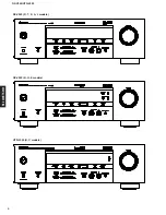
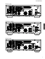
Page 6: ...RX V359 HTR 5930 6 RX V359 HTR 5930 RX V359 K model RX V359 R model RX V359 T model ...
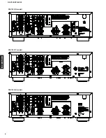
Page 7: ...RX V359 HTR 5930 7 RX V359 HTR 5930 RX V359 B G E models RX V359 A model RX V359 L model ...
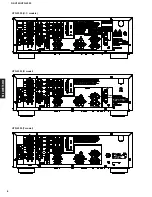
Page 8: ...RX V359 HTR 5930 8 RX V359 HTR 5930 HTR 5930 T model HTR 5930 U C models HTR 5930 R model ...
Page 9: ...RX V359 HTR 5930 9 RX V359 HTR 5930 HTR 5930 A model HTR 5930 K model HTR 5930 B G E models ...
Page 44: ...RX V359 HTR 5930 44 RX V359 HTR 5930 MEMO ...
Page 72: ...RX V359 HTR 5930 72 RX V359 HTR 5930 ...
Page 73: ...RX V359 HTR 5930 73 RX V359 HTR 5930 ...
Page 74: ...RX V359 HTR 5930 ...


