background image

2

2

SAFETY INSTRUCTIONS

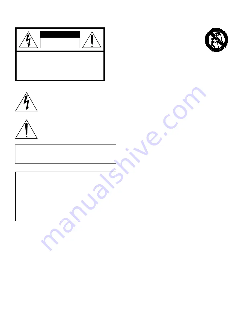
• Explanation of Graphical Symbols

The lightning flash with arrowhead symbol,
within an equilateral triangle, is intended to
alert you to the presence of uninsulated
“dangerous voltage” within the product’s
enclosure that may be of sufficient magnitude
to constitute a risk of electric shock to
persons.

The exclamation point within an equilateral
triangle is intended to alert you to the
presence of important operating and
maintenance (servicing) instructions in the
literature accompanying the appliance.

WARNING
TO REDUCE THE RISK OF FIRE OR ELECTRIC
SHOCK, DO NOT EXPOSE THIS UNIT TO RAIN OR
MOISTURE.

1

Read Instructions – All the safety and operating
instructions should be read before the unit is
operated.

2

Retain Instructions – The safety and operating
instructions should be retained for future reference.

3

Heed Warnings – All warnings on the unit and in the
operating instructions should be adhered to.

4

Follow Instructions – All operating and other
instructions should be followed.

5

Water and Moisture – The unit should not be used
near water – for example, near a bathtub, washbowl,
kitchen sink, laundry tub, in a wet basement, or near a
swimming pool, etc.

6

Carts and Stands – The unit should be used only with
a cart or stand that is recommended by the
manufacturer.

6A

A unit and cart combination should be
moved with care. Quick stops,
excessive force, and uneven surfaces
may cause the unit and cart
combination to overturn.

7

Wall or Ceiling Mounting – The unit
should be mounted to a wall or ceiling only as
recommended by the manufacturer.

8

Ventilation – The unit should be situated so that its
location or position does not interfere with its proper
ventilation.  For example, the unit should not be
situated on a bed, sofa, rug, or similar surface, that
may block the ventilation openings; or placed in a
built-in installation, such as a bookcase or cabinet that
may impede the flow of air through the ventilation
openings.

9

Heat – The unit should be situated away from heat
sources such as radiators, stoves, or other appliances
that produce heat.

10

Power Sources – The unit should be connected to a
power supply only of the type described in the
operating instructions or as marked on the unit.

11

Power-Cord Protection – Power-supply cords should
be routed so that they are not likely to be walked on or
pinched by items placed upon or against them, paying
particular attention to cords at plugs, convenience
receptacles, and the point where they exit from the
unit.

12

Cleaning – The unit should be cleaned only as
recommended by the manufacturer.

13

Nonuse Periods – The power cord of the unit should
be unplugged from the outlet when left unused for a
long period of time.

14

Object and Liquid Entry – Care should be taken so
that objects do not fall into and liquids are not spilled
into the inside of the unit.

15

Damage Requiring Service – The unit should be
serviced by qualified service personnel when:

A.

The power-supply cord or the plug has been
damaged; or

B.

Objects have fallen, or liquid has been spilled into
the unit; or

C.

The unit has been exposed to rain; or

D.

The unit does not appear to operate normally or
exhibits a marked change in performance; or

E.

The unit has been dropped, or the cabinet
damaged.

16

Servicing – The user should not attempt to service the
unit beyond those means described in the operating
instructions. All other servicing should be referred to
qualified service personnel.

17

Power Lines – An outdoor antenna should be located
away from power lines.

18

Grounding or Polarization – Precautions should be
taken so that the grounding or polarization is not
defeated.

IMPORTANT!
Please record the serial number of this unit in the
space below.

Model:
Serial No.:

The serial number is located on the rear of the unit.
Retain this Owner’s Manual in a safe place for future
reference.

CAUTION

RISK OF ELECTRIC SHOCK

DO NOT OPEN

  CAUTION:  TO REDUCE THE RISK OF

ELECTRIC SHOCK, DO NOT REMOVE

  COVER (OR BACK). NO USER-SERVICEABLE

PARTS INSIDE. REFER SERVICING TO

QUALIFIED SERVICE PERSONNEL.

Summary of Contents for KX-M5

Page 1: ...KX M5 OWNER S MANUAL MODE D EMPLOI Cassette Deck Platine Cassette UCAB ...

Page 2: ...air through the ventilation openings 9 Heat The unit should be situated away from heat sources such as radiators stoves or other appliances that produce heat 10 Power Sources The unit should be connected to a power supply only of the type described in the operating instructions or as marked on the unit 11 Power Cord Protection Power supply cords should be routed so that they are not likely to be w...

Page 3: ...o coaxial type cable If these corrective measures do not produce satisfactory results please contact the local retailer authorized to distribute this type of product If you can not locate the appropriate retailer please contact Yamaha Electronics Corp U S A 6660 Orangethorpe Ave Buena Park CA 90620 The above statements apply ONLY to those products distributed by Yamaha Corporation of America or it...

Page 4: ...ting the unit to the CRX M5 5 Using the remote control transmitter of the CRX M5 6 Turning on off the unit 6 When you connect the unit to CRX M5 Remote control Capability Automatic Synchronized Recording Timer Play Sleep Timer Recording Using Timer Playing CDs Getting Started SUPPLIED ACCESSORIES Dolby noise reduction manufactured under license from Dolby Laboratories Licensing Corporation DOLBY a...

Page 5: ...nit Using this unit with a higher voltage than that which is specified is dangerous and may result in a fire or other type of accident causing damage YAMAHA will not be held responsible for any damage resulting from use of this unit with a voltage other than that which is specified Keep this manual in a safe place for future reference Never allow metallic items e g screwdrivers tools etc to come n...

Page 6: ... indicators 7 9 eject button 7 DOLBY NR button 7 MODE switch 7 REC PAUSE button 9 2 reverse play button 7 7 stop button 7 3 forward play button 7 REAR PANEL 1 LINE OUT jacks 5 2 LINE IN jacks 5 3 AC power cord 5 4 SYSTEM CONNECTOR jack 5 5 VOLTAGE SELECTOR switch 3 General model only LINE OUT LINE IN A B L R SYSTEM CONNECTOR VOLTAGE SELECTOR 115 V 230 V STANDBY ON DOLBY NR MODE REC MUTE REC PAUSE ...

Page 7: ...he wall outlet until all other connections are completed Follow the steps as shown below to connect the unit to the CRX M5 using the supplied cords and accessories 1 Connect A to A and B to B using the audio connecting cords Insert the plugs into the jacks of the same color The two audio connecting cords are the same so you can connect A or B using either cord 2 Connect the unit and the CRX M5 wit...

Page 8: ... on the front panel to turn on off the unit When you turn off the CRX M5 the unit turns off automatically as it is connected to the CRX M5 with the system cable STANDBY ON DOLBY NR MODE REC MUTE REC PAUSE STANDBY ON Buttons for operation of the unit 3 To play back 2 To playback bottom side 7 To stop playback 1 To searching fast forward and rewind REC PAUSE To recording REC MUTE To make the non rec...

Page 9: ...onding MODE indicator lights up as follows One side of the tape is played back Both sides of the tape are played back Both sides of the tape are played back repeatedly 7 Press 3 to start play Press 2 to play the bottom side Selected tape direction indicator lights up DOLBY NR Dolby Noise Reduction is an extremely effective method of reducing undesirable background hiss on tapes The unit incorporat...

Page 10: ...nd to search for the beginning of the current track during play mode Notes The blank interval between selections must be at least 4 seconds long Searching function may not operate properly with tapes recorded at a low recording level or which have excessive noise When you play the beginning part or end part of the tape the search function may not work correctly 1 Press STANDBY ON to turn on the un...

Page 11: ...e tape direction indicator 3 lights up If you want to record starting from the bottom side press 2 so that the tape direction indicator 2 lights up 9 Start playing on the source component To stop recording Press 7 To pause recording Press REC PAUSE To resume recording press REC PAUSE again Note When you want to reduce the hiss noise in low level high frequency signals set DOLBY NR to ON When you r...

Page 12: ...D SYNC 8 Press 41 so that CD TAPE appears in the display of the CRX M5 9 Press CD SYNC The unit starts CD play from the beginning of the disc and the unit starts recording automatically You can record a CD in various modes For details refer the instructions of the CRX M5 To stop CD synchronized recording Press 7 TUNER CD or 7 TAPE Notes You can edit the tracks on a CD to be recorded so that they w...

Page 13: ...surface with your finger since dirt or finger oil will contaminate the deck s heads Cassette tapes There are many different types of cassette tapes available However they all conform to standard specifications so any brand may be used with the unit Classification of Cassette Tapes by Formulation Cassette tapes are available in four basic types depending of their formulation or type of magnetic mat...

Page 14: ...the beginning of desired track of the tape CAUSE There is an influence of strong external noise lightning excessive static electricity etc or a misoperation was performed while using the unit Slack tape wrapped around pinch roller Erasure prevention tab is broken off Head is dirty Head is dirty Head has become magnetized Tape is worn Tape encoded with DOLBY NR is played back with the unit s DOLBY ...

Page 15: ...s of production Specifications Type Auto reverse 4 track 2 channel recording and playback stereo cassette deck Heads Recording playback Hard permalloy x 1 Erase Double gap Ferrite x 1 Tape speed 4 76 cm sec Noise reduction Dolby B type NR General Power supply U S A and Canada models AC 120 V 60 Hz Australia model AC 240 V 50 Hz U K Europe and Singapore models AC 230 V 50 Hz General model AC 115 23...

Page 16: ...GEN BEI HAMBURG F R OF GERMANY YAMAHA ELECTRONIQUE FRANCE S A RUE AMBROISE CROIZAT BP70 CROISSY BEAUBOURG 77312 MARNE LA VALLEE CEDEX02 FRANCE YAMAHA ELECTRONICS UK LTD YAMAHA HOUSE 200 RICKMANSWORTH ROAD WATFORD HERTS WD1 7JS ENGLAND YAMAHA SCANDINAVIA A B J A WETTERGRENS GATA 1 BOX 30053 400 43 VÄSTRA FRÖLUNDA SWEDEN YAMAHA MUSIC AUSTRALIA PTY LTD 17 33 MARKET ST SOUTH MELBOURNE 3205 VIC AUSTRAL...

Reviews: