30
AN200
C-3 SW & LED
Press the panel switches according to the order indicated by the LCD
and confirm that all switches are working properly. Confirm that the
LED corresponding to the panel switch lights on.
After about one second, LED display and all LED’s light on for about
three seconds and then off to indicate following on the display:
Sine waves sound while the panel switches are being pressed on ac-
cording to the order indicated by the LED display. When another
switch, which is not indicated by the LED display, is pressed, the test
stops. The test advances to the next switch test when a correct switch
is pressed.
The “OK” will appear when all switches are normal.
The order of the switch check is shown below.
[SONG] > [PATTERN] > [SHOW VALUE] > [STORE] > [EXIT] > [SCENE
1] > [FREE EG LENGTH] > [FREE EG 1] > [FREE EG 2] > [SCENE 2] >
[FREE EG MODE] > [FREE EG 3] > [FREE EG 4] > [LFO DETAIL] > [EG
SELECT] > [DIST SWITCH] > [COMMON KEY ASGN] > [VCO1 WAVE]
> [SYNC MODE] > [VCO2 WAVE] > [EFFECT_TYPE] > [RE-TRIGGER]
> [TAP] > [TOP] > [SWING] > [REVERSE] > [SHIFT] > [OCT<<] > [OCT>>]
> [KEYBOARD] > [PATTERN SELECT] > [SYNTH TRACK] >
[RHYTHM TRACK] > [STEP 1-8] > [1 ] > [2] > [3] > [4] > [5] > [6] > [7] > [8]
> [STEP 9-16] > [9] > [10] > [11] > [12] > [13] > [14] > [15] > [16]
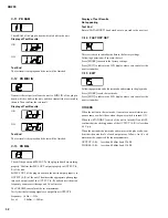
Display of Test Results
OK:
NG:
Test End
When all switches are checked normally, the “OK” is displayed and
the test will be finished.
C-4 DATA ENTRY
Rotate slowly the knob for DATA ENTRY clockwise until the value
23 appears on the LED display. When 23 appears, a sine wave sounds.
After this, rotate slowly the knob counterclockwise to confirm that a
sine wave sounds again and the “OK” is displayed on the LED when
the value becomes 0 (zero).
Display of Test Results
OK:
NG:
Test End
The test result is displayed and the test will be finished.
Refer to “The test procedure when an error is detected” when “NG”
(No Good) error is detected.
C-5 KNOB
Rotate slowly the knob indicated by LED display clockwise and then
counterclockwise to confirm that the value on the LED increases
from 0 to 255 and then decreases from 255 to 0 respectively.
When one knob is confirmed to work properly, a sine wave sounds
and the name of the next knob will appear on the LED.
The “OK” will appear when all knobs are normal.
The order of the knob check is shown below.
[SCENE] > [SPEED] > [ATTACK] > [DECAY] > [SUSTAIN] > [RE-
LEASE] > [PARAM] > [WET/VOL] > [PORTAMENTO] > [VCO1/
2] > [FM DEPTH] > [SYNC PITCH] > [NOISE LEVEL] > [CUT OFF]
> [RESONANCE] > [FEG DEPTH]
Display of Test Results
OK:
NG:
Test End
The test result is displayed and the test will be finished.
Refer to “The test procedure when an error is detected” when “NG”
(No Good) error is detected.
Summary of Contents for Loopfactory AN200
Page 20: ...20 AN200 DM CIRCUIT BOARD ...
Page 21: ...21 AN200 Pattern side 2NA V625760 2 ...
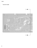
Page 24: ...24 AN200 PN CIRCUIT BOARD ...
Page 34: ...34 AN200 ...
Page 35: ...35 AN200 ...
Page 36: ...36 AN200 ...
Page 37: ...37 AN200 ...
Page 38: ...38 AN200 ...
Page 39: ...39 AN200 ...


