background image

LS2000/LX210/AR210

LIT-18616-SB-01

                                 1999~2003
ALL LST1200 (LS2000) MODELS

Summary of Contents for LS2000

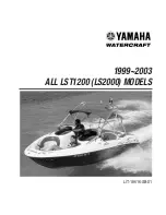
Page 1: ...LS2000 LX210 AR210 LIT 18616 SB 01 1999 2003 ALL LST1200 LS2000 MODELS ...

Page 2: ......

Page 3: ......

Page 4: ......

Page 5: ......

Page 6: ......

Page 7: ......

Page 8: ......

Page 9: ......

Page 10: ......

Page 11: ......

Page 12: ......

Page 13: ......

Page 14: ......

Page 15: ......

Page 16: ......

Page 17: ......

Page 18: ......

Page 19: ......

Page 20: ......

Page 21: ......

Page 22: ......

Page 23: ......

Page 24: ......

Page 25: ......

Page 26: ......

Page 27: ......

Page 28: ......

Page 29: ......

Page 30: ......

Page 31: ......

Page 32: ......

Page 33: ......

Page 34: ......

Page 35: ......

Page 36: ......

Page 37: ......

Page 38: ......

Page 39: ......

Page 40: ......

Page 41: ......

Page 42: ......

Page 43: ......

Page 44: ......

Page 45: ......

Page 46: ......

Page 47: ......

Page 48: ......

Page 49: ......

Page 50: ......

Page 51: ......

Page 52: ......

Page 53: ......

Page 54: ......

Page 55: ......

Page 56: ......

Page 57: ......

Page 58: ......

Page 59: ......

Page 60: ......

Page 61: ......

Page 62: ......

Page 63: ......

Page 64: ......

Page 65: ......

Page 66: ......

Page 67: ......

Page 68: ......

Page 69: ......

Page 70: ......

Page 71: ......

Page 72: ......

Page 73: ......

Page 74: ......

Page 75: ......

Page 76: ......

Page 77: ......

Page 78: ......

Page 79: ......

Page 80: ......

Page 81: ......

Page 82: ......

Page 83: ......

Page 84: ......

Page 85: ......

Page 86: ......

Page 87: ......

Page 88: ......

Page 89: ......

Page 90: ......

Page 91: ......

Page 92: ......

Page 93: ......

Page 94: ......

Page 95: ......

Page 96: ......

Page 97: ......

Page 98: ......

Page 99: ......

Page 100: ......

Page 101: ......

Page 102: ......

Page 103: ......

Page 104: ......

Page 105: ......

Page 106: ......

Page 107: ......

Page 108: ......

Page 109: ......

Page 110: ......

Page 111: ......

Page 112: ......

Page 113: ......

Page 114: ......

Page 115: ......

Page 116: ......

Page 117: ......

Page 118: ......

Page 119: ......

Page 120: ......

Page 121: ......

Page 122: ......

Page 123: ......

Page 124: ......

Page 125: ......

Page 126: ......

Page 127: ......

Page 128: ......

Page 129: ......

Page 130: ......

Page 131: ......

Page 132: ......

Page 133: ......

Page 134: ......

Page 135: ......

Page 136: ......

Page 137: ......

Page 138: ......

Page 139: ......

Page 140: ......

Page 141: ......

Page 142: ......

Page 143: ......

Page 144: ......

Page 145: ......

Page 146: ......

Page 147: ......

Page 148: ......

Page 149: ......

Page 150: ......

Page 151: ......

Page 152: ......

Page 153: ......

Page 154: ......

Page 155: ......

Page 156: ......

Page 157: ......

Page 158: ......

Page 159: ......

Page 160: ...2000 LST1200Y Supplementary Service Manual ...

Page 161: ...duced or transmitted in any form or by any means including photocopying and recording without the written permission of the copyright holder Such written permission must also be obtained before any part of this publication is stored in a retrieval system of any nature Printed in U S A Specifications features and options subject to change without notice 99 336 ...

Page 162: ...for the LST1200Y For complete service information it is necessary to use this Supplementary Service Manual together with the following manual LST1200X SERVICE MANUAL LIT 18616 02 06 For what is not mentioned in this manual please refer to the descriptions for LST1200 in the above Service Manual ...

Page 163: ...ECTRICAL 5 COOLING WATER FLOW DIAGRAM 7 TIGHTENING TORQUE 8 SPECIFIED TORQUE 8 GENERAL TORQUE 10 PERIODIC INSPECTION AND ADJUSTMENT JET PUMP UNIT 11 CLEAN OUT CAP INSPECTION 11 FUEL SYSTEM FUEL AND OIL SYSTEM 12 EXPLODED DIAGRAM 12 PREPARATION FOR REMOVAL 12 FUEL TANK 13 EXPLODED DIAGRAM 13 REMOVAL AND INSTALLATION CHART 13 FUEL SYSTEM 14 EXPLODED DIAGRAM 14 REMOVAL AND INSTALLATION CHART 15 FUEL ...

Page 164: ...GRAM 28 REMOVAL AND INSTALLATION CHART 29 SWITCH AND COMPONENT 30 WIRING DIAGRAM 30 STEREO 31 EXPLODED DIAGRAM 31 REMOVAL AND INSTALLATION CHART 31 SERVICE POINTS 32 STEREO REMOTE CONTROL 33 HULL AND DECK BIMINI TOP 34 EXPLODED DIAGRAM 34 REMOVAL AND INSTALLATION CHART 35 REMOTE CONTROL SYSTEM 36 EXPLODED DIAGRAM 36 REMOVAL AND INSTALLATION CHART 37 HATCH FITTINGS 38 EXPLODED DIAGRAM 38 REMOVAL AN...

Page 165: ...icant and location of lubrica tion point Apply Yamaha 2 stroke outboard motor oil Apply water resistant grease Yamaha grease A Yamaha marine grease Apply molybdenum disulfide grease Symbols to in an exploded diagram indi cate grade of sealing or locking agent and location of application point Apply Gasket Maker Apply Yamabond 4 Yamaha bond No 4 Apply LOCTITE No 271 Red LOCTITE Apply LOCTITE No 242...

Page 166: ...ed to the deck under the rear seat ENGINE SERIAL NUMBER The engine serial number is stamped on a label attached to the crankcase HULL IDENTIFICATION NUMBER H I N The H I N is stamped into the hull on the star board side of the stern GENERAL INFORMATION 1 1 GEN INFO Starting Primary I D Number F0R 100101 ...

Page 167: ...ntake system Reed valve Induction system Loop charge Lubrication system Oil injection Starting system Electric Spark plug NGK BR8HS Recommended battery Marine Grade Group 24 Battery capacity 12 volt 100Ah Jet Pump each Jet pump type Axial flow single stage Impeller material Stainless steel Impeller rotating direction seen from rear Counter clockwise Impeller pitch 15 1 Steering nozzle angle 23 1 F...

Page 168: ...41 0 100 0 105mm Wear limit in mm 0 0061 0 155mm Piston pin bore inside diameter in mm 0 7876 0 7884 20 004 20 025mm Piston Ring Top Type Keystone Dimensions B x T in mm 0 06 x 0 12 1 5 x 3 0mm End gap installed in mm 0 008 0 016 0 20 0 40mm Ring groove clearance installed in mm 0 001 0 003 0 02 0 07mm 2nd Type Keystone Dimensions B x T in mm 0 06 x 0 12 1 5 x 3 0mm End gap installed in mm 0 008 0...

Page 169: ...et M J 135 Pilot jet P J 100 01 95 02 97 5 03 Low speed screw turns out 1 1 4 Throttle valve 130 Valve seat size in mm 0 05 1 2mm High speed screw turns out 3 4 01 03 1 02 1 4 Trolling speed r min 1 300 50 Reed Valve Thickness in mm 0 02 0 5mm Valve stopper height in mm 0 49 0 01 12 5 0 2mm Valve warpage unit in mm 0 01 0 2mm Item Unit LST1200 Jet Pump each Impeller material SUS Number of impeller...

Page 170: ...ing V 2 4 min Peak voltage 2000 RPM V 11 1 min Peak voltage 3500 RPM V 21 1 min Charge Coil 1 Test points Color code Br B R Resistance Ω 172 0 258 0 Peak voltage open cranking V 22 3 min Peak voltage closed cranking V 21 0 min Peak voltage 2000 RPM V 46 4 min Peak voltage 3500 RPM V 65 2 min Charge Coil 2 Test points Color code L B R Resistance Ω 656 0 984 0 Peak voltage open cranking V 90 2 min P...

Page 171: ...Ω color 2 7 4 1 High tension cord B Rectifier Regulator Regulated voltage V 14 5 15 5 Thermo Switch On temperature F C 194 205 F 90 96 C Off temperature F C 194 168 8 F 90 76 C Starter Motor Brush length in mm 0 49 12 5mm Wear limit in mm 0 26 6 5mm Commutator undercut in mm 0 028 0 7mm Limit in mm 0 01 0 2mm Commutator diameter in mm 1 10 28 0mm Limit in mm 1 06 27mm Fuse Main Accessory Lead 12V ...

Page 172: ...the cylinder head Part of the cooling water is drained from the exhaust joint to the exhaust outlet at the back of the hull The remaining cooling water is used to cool the sides of muffler 2 and the exhaust outer cover Afterward it is mixed with the exhaust gas at the back of the exhaust outer cover then drained to the water lock These two ways of draining the cooling water from the engine create ...

Page 173: ... 2nd Bolt M8 2 40 4 0 29 Muffler 1 1st 15 1 5 11 2nd Bolt M8 12 30 3 0 22 Exhaust Outer Cover 1 1st 15 1 5 11 2nd Bolt M8 6 30 3 0 22 1st 23 2 3 17 Cylinder body 2nd Bolt M10 8 40 4 0 29 Cylinder head 1st 15 1 5 11 2nd Bolt M8 14 32 3 2 23 1st 15 1 5 11 2nd Bolt M8 15 30 3 0 22 Cylinder head cover 1st 4 0 4 2 9 2nd Bolt M6 2 8 0 8 5 8 Spark plug Bolt M14 3 25 2 5 18 Flywheel bolt Bolt M10 1 70 7 0...

Page 174: ...d Cap Bolt M6 3 4 0 4 2 9 Coupling Nut M27 1 37 3 7 27 Intermediate housing Bolt M8 3 17 1 7 12 Carburetor Carburetor to Base Bolt M6 6 5 0 5 3 6 Throttle Shaft Nut 3 4 0 4 2 9 Main Jet Jet 3 2 0 2 1 4 Pilot Jet Jet 3 1 0 1 0 7 Body Assembly Screw 3 2 0 2 1 4 Needle Valve Assembly Screw 3 1 0 1 0 7 Diaphragm Cover Screw M5 12 4 0 4 2 9 Fuel Pump Cover Screw M5 12 5 0 5 3 6 Deck Controls Remote Con...

Page 175: ...ge tighten multifastener assemblies in a criss cross fashion in progres sive stages until the specified torque is reached 10 General Torque Nut A Bolt B Specifications Nm M kg ft lb 8 mm M5 5 0 0 5 3 6 10 mm M6 8 0 0 8 5 8 12 mm M8 18 1 8 13 14 mm M10 36 3 6 25 17 mm M12 43 4 3 31 B A General Torque Bolt Specifications Dia Nm M kg ft lb 6 32 1 1 0 11 0 8 8 32 2 3 0 23 1 65 10 24 2 6 0 26 1 9 1 4 2...

Page 176: ...lding the cap by the T handle insert into the opening until fully seated Firmly press the T handle till the cap locks in place Firmly pull up on the T handle to verify the cap has locked securely in place Be sure the cap is properly positioned and locked in place Otherwise the cap could loosen and be forced out of the access ports by water pressure causing loss of perfor mance and possible damage ...

Page 177: ... 5 Port Fuel Filter 6 Starboard Fuel Filter 7 Oil Tank 8 Port Oil Pump 9 Starboard Oil Pump 10 Port Oil Filter 11 Starboard Oil Filter 12 Res Fuel Pickup 13 Fuel Return PREPARATION FOR REMOVAL Petrol gasoline is highly flammable and explosive Handle with special care Place the fuel cock in the OFF position Remove the battery Loosen the fuel filler cap WARNING ...

Page 178: ...Refer to SEAT FITTINGS in Chapter 8 1 Hose Band 2 2 Fuel Filler Hose 1 3 Hose Band 1 4 Air Vent Hose 1 NOTE Secure to tank stay bracket with zip tie on reassembly 5 Hose Band 4 6 Fuel Pipe 4 NOTE Label hose position for reassembly 7 Hose Band 2 8 Fuel Return Pipe 2 9 Machine Screw 8 10 Tapping Screw 8 11 Tank Stay Bracket 4 12 Fuel Sender Lead 1 Disconnect wire lead 13 Fuel Tank Assembly 1 Reverse...

Page 179: ...14 FUEL SYSTEM EXPLODED DIAGRAM FUEL SYSTEM x 4 FUEL ...

Page 180: ...ad cut in half is placed on each side of the forward tank stays Remote Control Assembly 1 Remove for Fuel Petcock Access Refer to REMOTE CONTROL UNIT in Chapter 3 9 Fuel Hose 1 4 Pickup NOTE Label the hose position for reassembly 10 Fuel Hose 2 2 To Filter 11 Fuel Petcock 2 12 Fuel Filter 2 Arrow direction faces fuel pump 13 Fuel Hose 3 2 To Carburetor Seat Back Cushion 1 Remove for inspection pla...

Page 181: ...16 FUEL PUMP EXPLODED DIAGRAM FUEL SYSTEM 4 FUEL ...

Page 182: ...ollow the Step order for removal Carburetor Assembly Refer to CARBURETOR REMOVAL 1 Pump Cover 1 2 Gasket 1 3 Clear Diaphragm 1 4 O ring 1 5 Diaphragm Body Assembly 1 6 Check Valve 2 7 Bushing Fuel Pump 2 8 Diaphragm 1 9 O Ring 1 10 Filter 1 Reverse the removal steps for installation FUEL SYSTEMx 4 FUEL ...

Page 183: ...installation instructions in JET PUMP UNIT INSPECTION Chapter 3 2 Screw 15 3 Clean out Tray 1 4 Hatch Interlock Switch 1 Set height a 0 5 12 5mm 5 Clamp 1 Set height b 1 2 30 5mm Set height c 0 0 0 12 0 0 3 0mm NOTE Hose and clamp must be positiioned below the clean out cap slots 6 Hose 1 Reverse the removal steps for installation REMOVAL AND INSTALLATION CHART JET PUMPx 6 JET PUMP ...

Page 184: ...19 ELECTRICAL SYSTEM x 7 ELEC ELECTRICAL SYSTEM WIRING DIAGRAM ...

Page 185: ...20 ELECTRICAL SYSTEM 7 ELEC HULL HARNESS ...

Page 186: ...PLACEMENT 1 Battery Leads 2 2 Blower Motor Leads 2 3 Hull harness to Deck harness 1 Access Engine compartment connector Clean out tray 1 Refer to JET PUMP CLEAN OUT PORTS in Chapter 6 4 Bilge pump Leads 2 5 Hull Harness 3 1 Reverse the removal steps for installation SERVICE POINTS Secure the harness to the bulkhead with zip ties ...

Page 187: ...22 ENGINE HARNESS ELECTRICAL SYSTEM 7 ELEC ...

Page 188: ...o wire lead 3 Access Engine compartment extension connector from engine Clean out tray Refer to JET PUMP CLEAN OUT PORTS in Chapter 6 3 Hatch switch with harness 1 Lanyard Extension Harness Replacement ea 1 Lanyard extension harness to 2 Access Helm pod main switch connectors Remote control assembly Refer to REMOTE CONTROL SYSTEM in Chapter 8 2 Lanyard switch to extension 2 harness connectors Reve...

Page 189: ...24 DECK HARNESS ELECTRICAL SYSTEM 7 ELEC ...

Page 190: ...leads 2 Access Helm pod 5 Deck harness to harness lead 1 1 connector 6 Deck harness to harness lead 2 1 connector 7 Bow light socket 2 Disconnect leads 8 Deck harness 1 Reverse the removal steps for installation SERVICE POINTS NOTE Removal of all old harness s may not be pos sible Secure the harness where possible in the same method as the old harness Where this is not possible secure to the old h...

Page 191: ...26 ELECTRICAL SYSTEM 7 ELEC STEREO HARNESS ...

Page 192: ...r accessory outlet Pu R and B leads 5 Stereo harness 5 to accessory 2 Access Passenger pod outlet leads 6 Stereo harness 5 to stereo 2 harness 6 connectors 7 Stereo harness 5 to stereo 1 keypad connector 8 Stereo harness 5 1 Reverse the removal steps for installation SERVICE POINTS NOTE Removal of all old harness s may not be possi ble Secure the harness where possible in the same method as the ol...

Page 193: ...EL BACK VIEW WIRING DIAGRAM ELECTRICAL SYSTEM 7 ELEC 1 Starboard Tach 2 Speedometer 3 Port Tach 4 Fuel Gauge 5 Horn Switch 6 Nav Lights Switch 7 Courtesy Light Switch 8 Radio Switch 9 Bilge Switch Blower Switch 10 ...

Page 194: ...connect Wiring 1 Set Screw 2 2 Choke Knob 2 3 Nut 2 4 Choke Cable 2 5 Nut 2 6 Main Switch 2 7 Nut w washer 8 8 Meter Panel Ass y 1 9 Nut w flat and lock washer 12 10 Tachometer 1 11 Speedometer 1 12 Fuel Gauge 1 13 Nut 6 14 Breaker 6 15 Switch 6 16 Switch Housing 6 Reverse the removal steps for installation REMOVAL AND INSTALLATION CHART ...

Page 195: ...rcuit Breaker 8 Radio 2 Stereo Switch 9 Courtesy Light 3 Courtesy Light Switch Blower Motor 4 Blower Switch Bilge Pump 5 Bilge Pump Switch Horn 6 Horn Switch Stern Light 7 Navigation Light Switch Bow Light ELECTRICAL SYSTEM 7 ELEC 11 12 10 13 14 ...

Page 196: ...Stereo harness 6 connector 1 4 Stereo remote connector 1 5 Antenna connector 1 6 Screw machine 1 7 Screw tapping 1 8 Rear support strap 1 NOTE Strap should have sharp bends at each mounting point to reduce flex 9 Stereo 1 Use tool supplied with stereo to release 10 Stereo mount 1 NOTE Be sure to bend the mounting tabs over securely during re assembly 11 Stereo mount support plate 1 Reverse the rem...

Page 197: ...tch and wiring Disconnect Remote Keypad and retest Replace stereo No sound 1 Check Speakers and wiring Attenuator button Press reset button Disconnect Remote Keypad and retest Replace stereo Stereo does not respond Press the reset button Disconnect Remote Keypad and retest Replace stereo ELECTRICAL SYSTEM 7 ELEC Stereo Voltage Red R Black B Yellow Y Black B 12VDC ...

Page 198: ...ation Replace stereo remote control NOTE The remote control output will be a low voltage The voltage will pulse 1 time or puse repeated ly depending on which button on the remote is depressed 4 Access Remove remote control assembly Refer to Remote Control Unit System in Chapter 8 Remote Control Input Voltage Red R Black B 12V DC Remote Control Output Voltage Clear Clear 1 V DC 7 ELEC ...

Page 199: ...34 BIMINI TOP HULL AND DECK 8 HULL DECK ...

Page 200: ... top assembly 1 3 Pivot screw 4 4 Bimini canvas 1 5 Rivet 12 6 Pivot end 6 7 Rivet 8 8 Coupler 4 9 Rivet 4 10 Mounting pin cable 4 11 Support tube 6 12 Bumper 2 13 Machine screw 4 w washer and lock nut 14 Strap eye 2 15 Machine screw 8 w washer and lock nut 16 Mounting eye 4 Reverse the removal steps for installation REMOVAL AND INSTALLATION CHART HULL AND DECK 8 HULL DECK ...

Page 201: ...36 REMOTE CONTROL SYSTEM EXPLODED DIAGRAM HULL AND DECK 8 HULL DECK ...

Page 202: ...ntrol 1 3 Washer 4 4 Screw Flat Head 4 5 Clevis Pin 4 6 Screw Plate 2 7 Nut 1 8 Plate Retaining 2 9 Remote Control Assembly 1 10 Screw 1 11 Switch Neutral 1 CABLE REMOVAL 12 Clevis Assembly 4 13 Nut 4 14 Nut 2 15 Cable Throttle 2 16 Shaft Joint Ball 2 17 Nut 2 Clean out Tray Refer to JET PUMP CLEAN OUT PORTS in Chapter 6 18 Thru hull Fitting 2 19 Cable Shift 2 Reverse the removal steps for install...

Page 203: ...38 HATCH FITTINGS EXPLODED DIAGRAM HULL AND DECK 8 HULL DECK ...

Page 204: ...ing 2 7 Latch Plate 1 CLEAN OUT HATCH DISASSEMBLY 8 Screw Tapping 16 9 Clean out Hatch 1 10 Hinge 1 11 Latch 1 12 Screw Machine 2 13 Washer 2 14 Nut 2 15 Latch Plate 1 BOW HATCH DISASSEMBLY 16 Screw Tapping 8 17 Hinge 2 18 Hatch 1 19 Screw Pan Head 2 20 Latch 1 21 Screw Tapping 2 22 Latch Plate 1 GLOVE BOX DISASSEMBLY 23 Nut w washer 5 24 Glove Box Assembly 1 25 Seal 1 26 Latch 1 27 Screw Tapping ...

Page 205: ...40 HELM POD ASSEMBLY EXPLODED DIAGRAM HULL AND DECK 8 HULL DECK ...

Page 206: ...al Locker 2 3 Rivet w washer 3 4 Fire Extinguisher Case w cap 1 5 Screw 4 6 Latch 2 7 Seal Windshield 2 8 Windshield 2 9 Screw w washer and nut 4 10 Hinge 2 11 Screw w washer and nut 4 12 Latch Plate 2 13 Nut w washers 4 14 Mirror 2 15 Screw 2 16 Horn Grill 1 17 Horn 1 18 Courtesy light Reverse the removal steps for installation HULL AND DECKx 8 HULL DECK ...

Page 207: ...2001 LST1200Z Supplementary Service Manual ...

Page 208: ...duced or transmitted in any form or by any means including photocopying and recording without the written permission of the copyright holder Such written permission must also be obtained before any part of this publication is stored in a retrieval system of any nature Printed in U S A Specifications features and options subject to change without notice 00 180 ...

Page 209: ...te service information it is necessary to use this Supplementary Service Manual together with the following manual For what is not mentioned in this manual please refer to the descriptions for LST1200 in the above Service Manual LST1200X SERVICE MANUAL LIT 18616 02 06 LST1200Y SUPPLEMENTARY SERVICE MANUAL LIT 18616 02 23 ...

Page 210: ...M EXPLODED DIAGRAM 12 REMOVAL AND INSTALLATION CHART 13 JET PUMP JET PUMP CLEAN OUT PORTS EXPLODED DIAGRAM 14 CLEANOUT HATCH SWITCH INSPECTION REINSTALLATION 15 ELECTRICAL SYSTEM STEREO HARNESS 16 STEREO HARNESS 5 REPLACEMENT 17 METER PANEL BACK VIEW WIRING DIAGRAM 18 METER PANEL BACK VIEW EXPLODED DIAGRAM 19 INDICATOR PANEL WIRING DIAGRAM 20 INDICATOR PANEL 21 OVERHEAT WARNING 21 LOW OIL WARNING ...

Page 211: ...diagram indi cate grade of lubricant and location of lubrica tion point Apply Yamaha 2 stroke outboard motor oil Apply water resistant grease Yamaha grease A Yamaha marine grease Apply molybdenum disulfide grease Symbols to in an exploded diagram indi cate grade of sealing or locking agent and location of application point Apply Gasket Maker Apply Yamabond 4 Yamaha bond No 4 Apply LOCTITE No 271 R...

Page 212: ...to the deck under the rear seat ENGINE SERIAL NUMBER The engine serial number is stamped on a label attached to the crankcase HULL IDENTIFICATION NUMBER H I N The H I N is stamped into the hull on the star board side of the stern LST1200Z Starting Primary I D Number F0R 700101 GENERAL INFORMATION 1 GEN INFO ...

Page 213: ...tarting enrichment Intake system Reed valve Induction system Loop charge Lubrication system Oil injection Starting system Electric Spark plug NGK BR8HS Recommended battery Marine Grade Group 24 Battery capacity 12 volt 100Ah Jet Pump each Jet pump type Axial flow single stage Impeller material Stainless steel Impeller rotating direction seen from rear Counter clockwise Impeller pitch 15 1 Steering...

Page 214: ...mm 0 0039 0 0041 0 100 0 105mm Piston pin bore inside diameter in mm 0 7876 0 7884 20 004 20 025mm Piston Ring Top Type Keystone Dimensions B x T in mm 0 06 x 0 12 1 5 x 3 0mm End gap installed in mm 0 008 0 016 0 20 0 40mm Ring groove clearance installed in mm 0 001 0 003 0 02 0 07mm 2nd Type Keystone Dimensions B x T in mm 0 06 x 0 12 1 5 x 3 0mm End gap installed in mm 0 008 0 016 0 20 0 40mm R...

Page 215: ... jet M J 135 Pilot jet P J 100 F 95 C 97 5 R Low speed screw turns out 1 Throttle valve 130 Valve seat size in mm 0 05 1 2mm High speed screw turns out 3 4 F R 1 C Trolling speed r min 1 300 50 Reed Valve Thickness in mm 0 02 0 5mm Valve stopper height in mm 0 49 0 01 12 5 0 2mm Valve warpage unit in mm 0 01 0 2mm Item Unit LST1200 Jet Pump each Impeller material SUS Number of impeller blades 3 Im...

Page 216: ...closed cranking V 2 0 min Peak voltage 2000 RPM V 11 min Peak voltage 3500 RPM V 20 min Charge Coil 1 Test points Color code Br B R Resistance Ω 172 258 Peak voltage open cranking V 20 min Peak voltage closed cranking V 20 min Peak voltage 2000 RPM V 45 min Peak voltage 3500 RPM V 65 min Charge Coil 2 Test points Color code L B R Resistance Ω 656 984 Peak voltage open cranking V 90 min Peak voltag...

Page 217: ...lated voltage V 14 5 15 5 Thermo Switch On temperature F C 194 205 F 90 96 C Off temperature F C 168 194 F 76 90 C Starter Motor Brush length in mm 0 49 12 5mm Wear limit in mm 0 26 6 5mm Commutator undercut in mm 0 028 0 7mm Limit in mm 0 01 0 2mm Commutator diameter in mm 1 10 28 0mm Limit in mm 1 06 27mm Fuse Main Accessory Lead 12V 20 amp Engine 12V 10 amp Stereo remote control 12V 3 amp Light...

Page 218: ...O 4 13 Choke Cable Inspection Adjustment O O 3 5 Shift Cable Inspection Adjustment O O 3 3 Shift System Inspection Adjustment O O 3 4 FUEL SYSTEM Fuel Tank Inspection Cleaning O 4 2 Fuel Filter Cleaning Replacement O 3 6 Fuel Line Inspection O O 4 1 Trolling Speed Inspection Adjustment O O 3 6 Carburetor Setting Inspection Adjustment O O 3 7 OIL INJECTION SYSTEM Oil Injection System Inspection Cle...

Page 219: ...Port Fuel Filter 5 Starboard Fuel Filter 6 Oil Tank 7 Port Oil Pump 8 Starboard Oil Pump 9 Port Oil Filter 10 Starboard Oil Filter 11 Fuel Return PREPARATION FOR REMOVAL Petrol gasoline is highly flammable and explosive Handle with special care Place the fuel valves in the OFF position Remove the battery Loosen the fuel filler cap WARNING ...

Page 220: ...y Refer to SEAT FITTINGS in Chapter 8 1 Hose Band 2 2 Fuel Filler Hose 1 3 Hose Band 1 4 Air Vent Hose 1 NOTE Secure to tank stay bracket with zip tie on reassembly 5 Hose Band 2 6 Fuel Pipe 2 NOTE Label hose position for reassembly 7 Hose Band 2 8 Fuel Return Pipe 2 9 Machine Screw 8 10 Tapping Screw 8 11 Tank Stay Bracket 4 12 Fuel Sender 1 Disconnect wire lead 13 Fuel Tank Assembly 1 Reverse th...

Page 221: ...12 FUEL SYSTEM 4 FUEL FUEL SYSTEM EXPLODED DIAGRAM ...

Page 222: ...lve 2 3 Insert Fuel Tank 1 4 Gasket 1 5 Fuel Level Sensor 1 Remove wire connector counterclockwise 6 Pad Fuel Tank 22 FUEL SYSTEM DISASSEMBLY Follow the Step order for removal 7 Fuel Hose 1 2 Pickup 8 Fuel Hose 2 2 To Filter 9 Fuel Filter 2 Arrow direction faces fuel pump Seat Back Cushion 1 Remove for inspection plate access Inspection Plate 1 Refer to SEAT FITTINGS in Chapter 8 10 Fuel Filler Ho...

Page 223: ...MOVAL 1 Cap 2 NOTE Follow cap installation instructions in JET PUMP UNIT INSPECTION Chptr 3 2 Screw 15 3 Clean out Tray 1 NOTE 4 Hatch Interlock Switch 2 Set height a 0 5 12 7mm Follow instructions in CLEANOUT HATCH SWITCH INSPECTION REINSTALLATION this chapter 5 Hose 2 NOTE Thoroughly seal the hose to the cleanout casting with marine grade silicone sealant Reverse the removal steps for installati...

Page 224: ...e of the switch Rotate the nut 1 4 turn then back to its original position to distribute the glue 5 Reinstall the switch and install the top nut finger tight Apply a drop of Super Glue to the flat sides of each switch see photo on the left NOTE Due to Super Glue being an anaerobic type chemical when used in this manner will require 24 hours to reach a proper cure Do not allow any of the Super Glue...

Page 225: ...16 STEREO HARNESS ELECTRICAL SYSTEM 7 ELEC ...

Page 226: ...r accessory outlet Pu R and B leads 5 Stereo harness 5 to accessory 2 Access Passenger pod outlet leads 6 Stereo harness 5 to stereo 2 harness 6 connectors 7 Stereo harness 5 to stereo 1 keypad connector 8 Stereo harness 5 1 Reverse the removal steps for installation SERVICE POINTS NOTE Removal of all old harness s may not be possi ble Secure the harness where possible in the same method as the ol...

Page 227: ...IAGRAM 1 2 3 4 5 6 7 8 9 11 10 ELECTRICAL SYSTEM 7 ELEC 1 Starboard Tach 2 Speedometer 3 Port Tach 4 Fuel Gauge 5 Horn Switch 6 Nav Lights Switch 7 Courtesy Light Switch 8 Radio Switch 9 Bilge Switch Blower Switch Indicator Panel 10 11 ...

Page 228: ...oke Knob 2 3 Nut 2 4 Choke Cable 2 5 Nut 2 6 Main Switch 2 7 Nut w washer 8 8 Meter Panel Ass y 1 9 Nut w flat and lock washer 12 Apply Loctite 242 10 Tachometer 2 11 Speedometer 1 12 Fuel Gauge 1 13 Nut 6 14 Breaker 6 15 Switch 6 16 Switch Housing 6 17 Indicator Panel Ass y 1 Reverse the removal steps for installation REMOVAL AND INSTALLATION CHART METER PANEL BACK VIEW EXPLODED DIAGRAM ...

Page 229: ...20 ELECTRICAL SYSTEM 7 ELEC INDICATOR PANEL WIRING DIAGRAM 1 9 Pin Plug Connector 2 Indicator Panel 3 Warning Buzzer ...

Page 230: ...uzzer The warn ing lights will go out after a few seconds and the power on light will continue to glow dimly Not working Repair wiring or replace bulbs or indicator assembly as needed OVERHEAT WARNING 1 Check Disconnect the 9 pin indicator connec tor behind the instrument panel and test according to the table below Bulb glows and buzzer beeps 5 times Not working Repair wiring or replace indicator ...

Page 231: ...nute to activate warning LOW FUEL WARNING 1 Check Disconnect the 9 pin indicator connec tor behind the instrument panel and test according to the table below Bulb glows after 1 to 2 minutes and buzzer beeps 5 times Not working Repair wiring or replace indicator assembly as needed NOTE Delay circuit requires connection of more than one minute to activate warning Low Oil Warning Battery Leads Warnin...

Page 232: ...ink Black F O O E Oil Switch Continuity Leads Position Purple Yellow Top Bottom O O Fuel Level Sensor Resistance Float Position Leads Pink Black White Top 33 5Ω Center 103Ω Bottom 240Ω Low Fuel Level Switch Float Position Leads Pink Black Black White Float at 1 8 to Empty Switch Closed Float Above 1 8 Switch Open NOTE The float is at 1 8 position when the resistance from Pink to Black White is app...

Page 233: ...lysis 1 Battery is charged and its specific gravity is in specification 2 All wire connections are correct 3 Wiring connections are securely made and without any corrosion 4 Lanyard is installed on the engine stop switch 5 Fuel is coming to the carburetor Items to be checked 24 Trouble Mode ...

Page 234: ... Bilge hose 6 O Bilge strainer 6 O Bilge hose joint 6 ELECTRICAL O O O O O O Ignition system 7 O Starting system 7 O Indication system 7 O Charging system 7 O Bilge pump wiring and switch HULL AND HOOD O Steering Cables 8 O O Water lock 8 O O O Exhaust hose 8 O O Muffler 8 O Drain plug 8 IRREGULAR WARNING INDICATION ENGINE WILL NOT START ROUGH IDLING ENGINE STALLS ENGINE WILL NOT STOP POOR PERFORM...

Page 235: ... 2000 YAMAHA MOTOR CORPORATION USA LIT 18616 02 29 ...

Page 236: ...2002 LST1200A A A Supplementary Service Manual ...

Page 237: ...roduced or transmitted in any form or by any means including photocopying and recording without the written permission of the copyright holder Such written permission must also be obtained before any part of this publication is stored in a retrieval system of any nature Printed in U S A Specifications features and options subject to change without notice 00 180 ...

Page 238: ...s necessary to use this Supplementary Service Manual together with the following manual For what is not mentioned in this manual please refer to the descriptions for LST1200 in the above Service Manual LST1200X SERVICE MANUAL LIT 18616 02 06 LST1200Y SUPPLEMENTARY SERVICE MANUAL LIT 18616 02 23 LST1200Z SUPPLEMENTARY SERVICE MANUAL LIT 18616 02 29 ...

Page 239: ... HULL AND HOOD 7 ELECTRICAL 7 PERIODIC INSPECTION AND ADJUSTMENT MAINTENANCE INTERVAL CHART 9 ELECTRICAL SYSTEM STEREO HARNESS 10 STEREO HARNESS 5 REPLACEMENT 11 METER PANEL BACK VIEW WIRING DIAGRAM 12 METER PANEL BACK VIEW EXPLODED DIAGRAM 13 OIL SWITCH 14 FUEL GAUGE 14 FUEL LEVEL SENSOR LOW OIL SWITCH 14 TROUBLE ANALYSIS TROUBLE ANALYSIS 15 WIRING DIAGRAM 16 ...

Page 240: ...diagram indi cate grade of lubricant and location of lubrica tion point Apply Yamaha 2 stroke outboard motor oil Apply water resistant grease Yamaha grease A Yamaha marine grease Apply molybdenum disulfide grease Symbols to in an exploded diagram indi cate grade of sealing or locking agent and location of application point Apply Gasket Maker Apply Yamabond 4 Yamaha bond No 4 Apply LOCTITE No 271 R...

Page 241: ...ENGINE SERIAL NUMBER The engine serial number is stamped on a label attached to the crankcase HULL IDENTIFICATION NUMBER H I N The H I N is stamped into the hull on the star board side of the stern LST1200A LS2000 Starting Primary I D Number F0R 750101 LST1200A A LX2000 Starting Primary I D Number F0R 703001 GENERAL INFORMATION 1 GEN INFO ...

Page 242: ...3 Starting enrichment Choke Plate Intake system Reed valve Induction system Loop charge Lubrication system Oil injection Starting system Electric Spark plug NGK BR8HS Recommended battery Marine Grade Group 24 Battery capacity 12 volt 100Ah Jet Pump each Jet pump type Axial flow single stage Impeller material Stainless steel Impeller rotating direction seen from rear Counter clockwise Impeller pitc...

Page 243: ...mm 0 0039 0 0041 0 100 0 105mm Piston pin bore inside diameter in mm 0 7876 0 7884 20 004 20 025mm Piston Ring Top Type Keystone Dimensions B x T in mm 0 06 x 0 12 1 5 x 3 0mm End gap installed in mm 0 008 0 016 0 20 0 40mm Ring groove clearance installed in mm 0 001 0 003 0 02 0 07mm 2nd Type Keystone Dimensions B x T in mm 0 06 x 0 12 1 5 x 3 0mm End gap installed in mm 0 008 0 016 0 20 0 40mm R...

Page 244: ... nozzle M N in mm 0 13 3 2mm Main jet M J 135 Pilot jet P J 100 F 95 C 97 5 R Throttle valve 130 Valve seat size in mm 0 05 1 2mm Trolling speed r min 1 300 50 Reed Valve Thickness in mm 0 02 0 5mm Valve stopper height in mm 0 49 0 01 12 5 0 2mm Valve warpage limit in mm 0 01 0 2mm Item Unit LST1200 Jet Pump each Impeller material SUS Number of impeller blades 3 Impeller pitch degree 15 1 Impeller...

Page 245: ...sed cranking V 2 0 min Peak voltage 2000 RPM V 11 min Peak voltage 3500 RPM V 20 min Charge Coil 1 Test points Color code Br B R Resistance Ω 172 258 Peak voltage open cranking V 20 min Peak voltage closed cranking V 20 min Peak voltage 2000 RPM V 45 min Peak voltage 3500 RPM V 65 min Charge Coil 2 Test points Color code L B R Resistance Ω 656 984 Peak voltage open cranking V 90 min Peak voltage c...

Page 246: ...lated voltage V 14 5 15 5 Thermo Switch On temperature F C 194 205 F 90 96 C Off temperature F C 168 194 F 76 90 C Starter Motor Brush length in mm 0 49 12 5mm Wear limit in mm 0 26 6 5mm Commutator undercut in mm 0 028 0 7mm Limit in mm 0 01 0 2mm Commutator diameter in mm 1 10 28 0mm Limit in mm 1 06 27mm Fuse Main Accessory Lead 12V 20 amp Engine 12V 10 amp Stereo remote control 12V 3 amp Light...

Page 247: ...O 4 13 Choke Cable Inspection Adjustment O O 3 5 Shift Cable Inspection Adjustment O O 3 3 Shift System Inspection Adjustment O O 3 4 FUEL SYSTEM Fuel Tank Inspection Cleaning O 4 2 Fuel Filter Cleaning Replacement O 3 6 Fuel Line Inspection O O 4 1 Trolling Speed Inspection Adjustment O O 3 6 Carburetor Setting Inspection Adjustment O O 3 7 OIL INJECTION SYSTEM Oil Injection System Inspection Cle...

Page 248: ...10 STEREO HARNESS ELECTRICAL SYSTEM 7 ELEC ...

Page 249: ...let leads 4 Stereo harness 5 to stereo 3 For accessory outlet Pur Red and B harness 6 connectors 5 Stereo harness 5 1 Reverse the removal steps for installation SERVICE POINTS NOTE Removal of all old harness s may not be possi ble Secure the harness where possible in the same method as the old harness Where this is not possible secure to the old har ness Cut and remove any old harness s that is ac...

Page 250: ...IEW WIRING DIAGRAM ELECTRICAL SYSTEM 7 ELEC 1 Starboard Tach 2 Speedometer 3 Port Tach 4 Fuel Gauge 5 Horn Switch 6 Nav Lights Switch 7 Courtesy Light Switch 8 Radio Switch 9 Bilge Switch Blower Switch Indicator Panel 10 11 ...

Page 251: ...oke Knob 2 3 Nut 2 4 Choke Cable 2 5 Nut 2 6 Main Switch 2 7 Nut w washer 8 8 Meter Panel Ass y 1 9 Nut w flat and lock washer 12 Apply Loctite 242 10 Tachometer 2 11 Speedometer 1 12 Fuel Gauge 1 13 Nut 6 14 Breaker 6 15 Switch 6 16 Switch Housing 6 17 Indicator Panel Ass y 1 Reverse the removal steps for installation REMOVAL AND INSTALLATION CHART METER PANEL BACK VIEW EXPLODED DIAGRAM ...

Page 252: ...h Continuity Leads Position Tan Black Black Top Bottom O O Fuel Level Sensor Resistance Float Position Leads Pink Black White Top 33 5Ω Center 103Ω Bottom 240Ω Low Fuel Level Switch Float Position Leads Pink Black Black White Float at 1 8 to Empty Switch Closed Float Above 1 8 Switch Open NOTE The float is at 1 8 position when the resistance from Pink to Black White is approximately 200Ω ELECTRICA...

Page 253: ...nalysis 1 Battery is charged and its specific gravity is in specification 2 All wire connections are correct 3 Wiring connections are securely made and without any corrosion 4 Lanyard is installed on the engine stop switch 5 Fuel is coming to the carburetor Items to be checked Trouble Mode ...

Page 254: ...Bilge hose 6 O Bilge strainer 6 O Bilge hose joint 6 ELECTRICAL O O O O O O Ignition system 7 O Starting system 7 O Indication system 7 O Charging system 7 O Bilge pump wiring and switch HULL AND HOOD O Steering Cables 8 O O Water lock 8 O O O Exhaust hose 8 O O Muffler 8 O Drain plug 8 IRREGULAR WARNING INDICATION ENGINE WILL NOT START ROUGH IDLING ENGINE STALLS ENGINE WILL NOT STOP POOR PERFORMA...

Page 255: ... 2001 YAMAHA MOTOR CORPORATION USA LIT 18616 02 41 ...

Page 256: ...2003 LST1200 B A B B B and D B Supplementary Service Manual LS2000 LX210 AR210 LS2000 LX210 AR210 ...

Page 257: ...be reproduced or transmitted in any form or by any means including photocopying and recording without the written permission of the copyright holder Such written permission must also be obtained before any part of this publication is stored in a retrieval system of any nature Printed in U S A Specifications features and options subject to change without notice 02 656 ...

Page 258: ... Supplementary Service Manual together with the following manual For what is not mentioned in this manual please refer to the descriptions for LST1200 in the above Service Manual LST1200X SERVICE MANUAL LIT 18616 02 06 LST1200Y SUPPLEMENTARY SERVICE MANUAL LIT 18616 02 23 LST1200Z SUPPLEMENTARY SERVICE MANUAL LIT 18616 02 29 LST1200A A A SUPPLEMENTARY SERVICE MANUAL LIT 18616 02 41 ...

Page 259: ... ELECTRICAL 7 PERIODIC INSPECTION AND ADJUSTMENT MAINTENANCE INTERVAL CHART 9 ELECTRICAL SYSTEM STEREO HARNESS 10 STEREO HARNESS 5 REPLACEMENT 11 METER PANEL BACK VIEW WIRING DIAGRAM LS LX 12 METER PANEL BACK VIEW WIRING DIAGRAM AR 13 HULL AND DECK EXTENDED SWIM STEP EXPLODED DIAGRAM 14 WAKEBOARD TOWER EXPLODED DIAGRAM 15 TROUBLE ANALYSIS TROUBLE ANALYSIS 16 WIRING DIAGRAM 17 ...

Page 260: ...diagram indi cate grade of lubricant and location of lubrica tion point Apply Yamaha 2 stroke outboard motor oil Apply water resistant grease Yamaha grease A Yamaha marine grease Apply molybdenum disulfide grease Symbols to in an exploded diagram indi cate grade of sealing or locking agent and location of application point Apply Gasket Maker Apply Yamabond 4 Yamaha bond No 4 Apply LOCTITE No 271 R...

Page 261: ...engine serial number is stamped on a label attached to the crankcase HULL IDENTIFICATION NUMBER H I N The H I N is stamped into the hull on the star board side of the stern LST1200 B LS2000 Starting Primary I D Number F0R 750101 LST1200A B B LX210 Starting Primary I D Number F0R 703001 LST1200D B AR210 Starting Primary I D Number FOR 730101 GENERAL INFORMATION 1 GEN INFO ...

Page 262: ... enrichment Choke Plate Intake system Reed valve Induction system Loop charge Lubrication system Oil injection Starting system Electric Spark plug NGK BR8HS Recommended battery Marine Grade Group 24 Battery capacity 12 volt 100Ah Jet Pump each Jet pump type Axial flow single stage Impeller material Stainless steel Impeller rotating direction seen from rear Counter clockwise Impeller pitch 15 1 Ste...

Page 263: ...mm 0 0039 0 0041 0 100 0 105mm Piston pin bore inside diameter in mm 0 7876 0 7884 20 004 20 025mm Piston Ring Top Type Keystone Dimensions B x T in mm 0 06 x 0 12 1 5 x 3 0mm End gap installed in mm 0 008 0 016 0 20 0 40mm Ring groove clearance installed in mm 0 001 0 003 0 02 0 07mm 2nd Type Keystone Dimensions B x T in mm 0 06 x 0 12 1 5 x 3 0mm End gap installed in mm 0 008 0 016 0 20 0 40mm R...

Page 264: ... nozzle M N in mm 0 13 3 2mm Main jet M J 135 Pilot jet P J 100 F 95 C 97 5 R Throttle valve 130 Valve seat size in mm 0 05 1 2mm Trolling speed r min 1 300 50 Reed Valve Thickness in mm 0 02 0 5mm Valve stopper height in mm 0 49 0 01 12 5 0 2mm Valve warpage limit in mm 0 01 0 2mm Item Unit LST1200 Jet Pump each Impeller material SUS Number of impeller blades 3 Impeller pitch degree 15 1 Impeller...

Page 265: ...sed cranking V 2 0 min Peak voltage 2000 RPM V 11 min Peak voltage 3500 RPM V 20 min Charge Coil 1 Test points Color code Br B R Resistance Ω 172 258 Peak voltage open cranking V 20 min Peak voltage closed cranking V 20 min Peak voltage 2000 RPM V 45 min Peak voltage 3500 RPM V 65 min Charge Coil 2 Test points Color code L B R Resistance Ω 656 984 Peak voltage open cranking V 90 min Peak voltage c...

Page 266: ...lated voltage V 14 5 15 5 Thermo Switch On temperature F C 194 205 F 90 96 C Off temperature F C 168 194 F 76 90 C Starter Motor Brush length in mm 0 49 12 5mm Wear limit in mm 0 26 6 5mm Commutator undercut in mm 0 028 0 7mm Limit in mm 0 01 0 2mm Commutator diameter in mm 1 10 28 0mm Limit in mm 1 06 27mm Fuse Main Accessory Lead 12V 20 amp Engine 12V 10 amp Stereo remote control 12V 3 amp Light...

Page 267: ...O 4 13 Choke Cable Inspection Adjustment O O 3 5 Shift Cable Inspection Adjustment O O 3 3 Shift System Inspection Adjustment O O 3 4 FUEL SYSTEM Fuel Tank Inspection Cleaning O 4 2 Fuel Filter Cleaning Replacement O 3 6 Fuel Line Inspection O O 4 1 Trolling Speed Inspection Adjustment O O 3 6 Carburetor Setting Inspection Adjustment O O 3 7 OIL INJECTION SYSTEM Oil Injection System Inspection Cle...

Page 268: ...10 STEREO HARNESS ELECTRICAL SYSTEM 7 ELEC 4 2 3 ...

Page 269: ...rness 5 to accessory 2 For accessory outlet Pur Red and B outlet leads 4 Stereo harness 5 1 Reverse the removal steps for installation SERVICE POINTS NOTE Removal of all old harness s may not be possi ble Secure the harness where possible in the same method as the old harness Where this is not possible secure to the old har ness Cut and remove any old harness s that is accessible to avoid confusio...

Page 270: ... LX210 MODELS WIRING DIAGRAM ELECTRICAL SYSTEM 7 ELEC 1 Starboard Tach 2 Speedometer 3 Port Tach 4 Fuel Gauge 5 Horn Switch 6 Nav Lights Switch 7 Courtesy Light Switch 8 Radio Switch 9 Bilge Switch Blower Switch Indicator Panel 10 11 ...

Page 271: ...C METER PANEL BACK VIEW AR10 Model WIRING DIAGRAM 1 Starboard Tach 2 Speedometer 3 Port Tach 4 Fuel Gauge 5 Horn Switch 6 Nav Lights Switch 7 Courtesy Light Switch 8 Radio Switch 9 Bilge Switch Blower Switch Indicator Panel 10 11 ...

Page 272: ...REMOVAL Remove cleanout tray for access to bracket fasteners 6 Nut 5 16 18 Nylon Lock 4 7 Washer 5 16 Flat 4 8 Screw 5 16 x 1 1 2 4 9 Bracket Plate 2 1 10 Nut 5 16 18 Nylon Lock 8 11 Washer 5 16 Flat 8 12 Screw 5 16 x 2 8 13 Bracket pump Pocket 2 Reverse the removal steps for installation Apply silicone sealant to bolts and washers REMOVAL AND INSTALLATION CHART 3 4 5 6 7 8 9 10 11 12 13 13 2 1 SW...

Page 273: ...Assembly 1 SUPPORT ASSEMBLIES 3 Nut 5 8 11 Nylon Lock 2 Access fasteners by removing storage tubs 4 Washer 5 8 Flat 2 5 Bolt 5 8 11 x 2 2 6 Nut 1 4 20 8 Access fasteners by removing inspection plate under rear seat backrest 7 Washer 1 4 Fender 8 8 Bolt 1 4 20 8 9 Packing Plate 4 10 Support Assembly 2 Reverse the removal steps for installation REMOVAL AND INSTALLATION CHART WAKEBOARD TOWER EXPLODED...

Page 274: ... and its specific gravity is in specification 2 All wire connections are correct 3 Wiring connections are securely made and without any corrosion 4 Lanyard is installed on the engine stop switch 5 Fuel is coming to the carburetor Items to be checked Trouble Mode TROUBLE ANALYSIS 9 TRBL ANLS ...

Page 275: ...6 O Bilge hose 6 O Bilge strainer 6 O Bilge hose joint 6 ELECTRICAL O O O O O O Ignition system 7 O Starting system 7 O Indication system 7 O Charging system 7 O Bilge pump wiring and switch HULL AND HOOD O Steering Cables 8 O O Water lock 8 O O O Exhaust hose 8 O O Muffler 8 O Drain plug 8 IRREGULAR WARNING INDICATION ENGINE WILL NOT START ROUGH IDLING ENGINE STALLS ENGINE WILL NOT STOP POOR PERF...

Page 276: ...LK ENGINE LEFT FREE OFF PUSH ON BRN BRN BLK WHT SHIFTER LEFT BRN BRN BLK BLU PURPLE LIGHT LIGHT LIGHT LIGHT BLUE SPEEDOMETER BLUE FUEL GAUGE OIL WARNING LIGHT RED BLK RED BLK RED BLK RED BLK RED BLK 5A 5A 5A 10A 5A 5A 5A COURTESY LIGHT SWITCH ORG ORG ORG ORG ORG ORG BLK GRY GRN BOW LIGHT BLK RED BLK RED BLK BLUE GRN STEREO SWITCH YEL RED BLK ANTENNA STEREO SYSTEM AR LX LS OPTIONAL RED BLK BLK BLK ...

Page 277: ... 2003 YAMAHA MOTOR CORPORATION USA LIT 18616 03 41 ...

Reviews: