background image

M2500

3

SPECIFICATIONS

General specifications

0 dB is referenced to 0.775 Vrms.

Total Harmonic Distortion

Less than 0.1% (THD+N)

(Master output)

20 Hz–20 kHz @ +14 dB 600 

Frequency Response

0+1, –3 dB

(Master Output)

20 Hz–20 kHz @ +4 dB 600 

Gain control at minimum level

Hum & Noise (20 Hz–20 kHz)*1

–128 dB Equivalent Input Noise.

Rs= 150 

–99 dB Residual Output Noise.

(STEREO OUT, MONO/C OUT, 

GROUP/AUX OUT, AUX OUT, 
AUX/GROUP OUT)

Input Gain= Max.
Input Pad= OFF
     ||
Input sensitivity= –60 dB

–64 dB(68 dB S/N) STEREO OUT  Master Level control and 

one Ch fader at nominal level.

–80 dB(84 dB S/N) STEREO OUT, MONO/C OUT Master fader 

at nominal level and all Ch assign SW’s off 
and all GROUP to ST SW’s off.

–81 dB(85 dB S/N) GROUP1/AUX7–GROUP8/AUX14 OUT 

Master Level control at nominal level and all 
Ch assign SW’s off.
GROUP/AUX FLIP SW off.

–75 dB(79 dB S/N) AUX1–6, AUX7/GROUP1–AUX14/GROUP8 

OUT Master Level control at nominal level 
and all Ch send controls at minimum.
GROUP/AUX FLIP SW off.

–90 dB(94 dB S/N) MATRIX OUT Master level control at nomi-

nal level and all Matrix Mix controls at mini-
mum level.

Crosstalk

–70 dB @ 1 kHz

adjacent inputs.

–70 dB @ 1 kH

input to output. (CH INPUT)

–50 dB @ 1 kHz

input to output. (ST CH INPUT)

Maximum Voltage Gain
GROUP/AUX FLIP SW= off

60 dB

CH INPUT to CH INSERT OUT

84 dB

CH INPUT to GROUP1/AUX7–GROUP8/
AUX14 OUT

80 dB

CH INPUT to AUX1, 2 OUT(Pre Fader)

90 dB

CH INPUT to AUX3–6, AUX7/GROUP1–
AUX14/GROUP8 OUT(Post Fader)

84 dB

CH INPUT to STEREO OUT(CH to ST)

70 dB

CH INPUT to MONITOR OUT(PFL)

CH INPUT PAD SW

26 dB

CH INPUT GAIN control

44 dB

variable

ST CH 1A, 2–4 INPUT GAIN control

40 dB

variable

ST CH 1B INPUT GAIN control

30 dB

variable

CH INPUT High Pass Filter

18 dB/octave

roll-off below 80 Hz at –3 dB point.

CH INPUT Equalization

+15, –15 dB maximum

HIGH

10 kHz (shelving)

HIGH-MID 400– 8 kHz (peaking)
LOW-MID 80–1.6 kHz (peaking)
LOW

100 Hz (shelving)

ST CH INPUT Equalization

+15, –15 dB maximum

HIGH

10 kHz (shelving)

LOW

100 Hz (shelving)

Phantom Power

+48 VDC is applied to balanced inputs (via 
6.8 k

 current-limiting/isolation resistors) for 

powering condenser microphones; may be 
turned ON or OFF via rear-panel phantom 
Master switch.
When Master is ON, individual channels 
may be turned ON or OFF via +48V 
switches (with red LED) on each input chan-
nel.

CH LED Indicators

PEAK

LED(red) built into each CH INPUT turns on 
when pre-Fader level r17 dB.

NOM

LED(yellow) built into each CH INPUT turns 
on when pre-Fader level reaches 0 dB.

SIGNAL

LED(green) built into each CH INPUT turns 
on when pre-Fader level reaches –13 dB.

ST CH LED Indicators

PEAK

LED(red) built into each ST CH INPUT turns 
on when pre-Fader [L+R] level reaches 
+17 dB.

NOM

LED(yellow) built into each ST CH INPUT 
turns on when pre-Fader [L+R] level 
reaches 0 dB.

SIGNAL

LED(green) built into each ST CH INPUT 
turns on when pre-Fader [L+R] level 
reaches –13 dB.

Oscillator/Noise

Switchable sine wave @ 100 Hz, 1 kHz or 
10 kHz, or pink noise.

Scene Memory

Direct Scene Memory recall switches (1–8)
Switchable Scene Memory recall (1–128)

VU Meters

11 illuminated meters
(0VU= +4 dB output @ 600

 load)

#1 ; GROUP1/AUX7

AUX1

AUX7/GROUP1

MATRIX1

#2 ; GROUP2/AUX8

AUX2

AUX8/GROUP2

MATRIX2

#3 ; GROUP3/AUX9

AUX3

AUX9/GROUP3

MATRIX3

#4 ; GROUP4/AUX10

AUX4

AUX10/GROUP4

MATRIX4

#5 ; GROUP5/AUX11

AUX5

AUX11/GROUP5

MATRIX5

#6 ; GROUP6/AUX12

AUX6

AUX12/GROUP6

MATRIX6

#7 ; GROUP7/AUX13

NONE

AUX13/GROUP7

MATRIX7

#8 ; GROUP8/AUX14

NONE

AUX14/GROUP8

MATRIX8

#9 ; STEREO L

PFL/AFL L

#10 ; MONO/C
#11 ; STEREO R

PFL/AFL R

VU Meter Peak Indicators

LED(red) built into each VU meter turns on 
when output signal is above the level 3 dB 
lower than clipping level.

Dimension

Heigt

265 mm

Depth

875 mm (except rear connectors)

Width

2385 mm(56C), 2142 mm(48C), 
1899 mm(40C), 1642 mm(32), 
1400 mm(24)

Weight

102kg(56C), 93kg(48C), 84kg(40C), 
71kg(32), 62kg(24)

*1 Hum & Noise are measured with a 6 dB/octave filter @ 12.7 kHz; 

equivalent to a 20 kHz filter with infinite dB/octave attenuation.

For European Model
Purchaser/User information specified in EN55103-1 and EN55103-2.
Conformed Enviroment: E1, E2, E3 and E4.

Summary of Contents for M2500-24

Page 1: ...S 61 69 TEST PROGRAM 76 78 ERROR MESSAGES 80 81 MIDI IMPLEMENTATION CHART 82 CIRCUIT DIAGRAMS PARTS LIST CONTENTS SERVICE MANUAL PA 011484 M2500 24 20000220 850000 M2500 32 20000220 1000000 M2500 40C 20000220 1150000 1 50K 5972 Printed in Japan 2000 02 HAMAMATSU JAPAN MIXING CONSOLE 1 2 M2500 48C 20000220 1300000 M2500 56C 20000220 1450000 PW3000MA 20000220 100000 M2500 56C ...

Page 2: ...y other entities to cause cancer and or birth defects or other reproductive harm DO NOT PLACE SOLDER ELECTRICAL ELECTRONIC OR PLASTIC COMPONENTS IN YOUR MOUTH FOR ANY REASON WHAT SO EVER Avoid prolonged unprotected contact between solder and your skin When soldering do not inhale solder fumes or expose eyes to solder flux vapor If you come in contact with solder or components located inside the en...

Page 3: ...mum HIGH 10 kHz shelving LOW 100 Hz shelving Phantom Power 48 VDC is applied to balanced inputs via 6 8 kΩ current limiting isolation resistors for powering condenser microphones may be turned ON or OFF via rear panel phantom Master switch When Master is ON individual channels may be turned ON or OFF via 48V switches with red LED on each input chan nel CH LED Indicators PEAK LED red built into eac...

Page 4: ... INPUT L R 20 10 kΩ 600 Ω Lines 40 dB 7 75 mV 20 dB 77 5 mV 0 dB 0 775 V Phono Jack 3 10 10 dB 245 mV 10 dB 2 45 V 30 dB 24 5 V ST CH INPUT L R 2 4 30 5 kΩ 600 Ω Lines 50 dB 2 45 mV 30 dB 24 5 mV 10 dB 245 mV Phone Jack TRS 4 10 10 dB 245 mV 10 dB 2 45 V 30 dB 24 5 V TALKBACK IN 10 kΩ 50 600 Ω Mics 66 dB 0 388 mV 50 dB 2 45 mV 20 dB 77 5 mV XLR 3 31 type 5 MATRIX SUB IN L R 10 kΩ 600 Ω Lines 2 dB ...

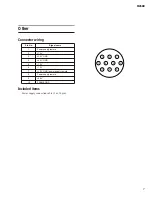
Page 5: ...Included items Power supply connection cable 3 m 10 pin Pin No Signal name 1 Power supply remote 2 15 V 3 15 V GND 4 48 V GND 5 15 V 6 12 V 7 12 V GND power supply remote 8 Power supply remote 9 48 V 10 FRAME GND 3 2 1 10 9 8 7 6 5 4 ...

Page 6: ...56C 1899 M2500 40C 1642 M2500 32 1400 M2500 24 2142 M2500 48C 875 137 270 270 597 597 792 422 88 55 55 847 847 792 768 154 88 55 55 968 968 792 768 399 88 55 55 740 740 700 792 768 399 331 55 55 718 718 792 422 331 55 55 M2500 32 M2500 24 M2500 56C M2500 48C M2500 40C ...

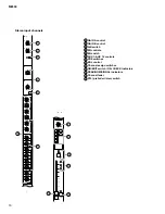
Page 7: ... 10 10 20 30 40 60 50 5 0 5 SIGNAL CHECK ON 1 2 3 4 5 6 7 8 PFL 0 10 AUX14 1 2 3 5 4 6 7 8 9 10 11 12 13 14 15 Monaural input channels PANEL LAYOUT Control panel Input channel section 48 V phantom power switch GAIN control 26 dB pad switch φ phase switch 80 high pass filter switch EQ controls EQ switch AUX 1 AUX 14 controls PRE switches PAN control Channel assign switches ON EDIT switch ON CHECK i...

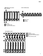
Page 8: ...isten switch 1 2 3 4 5 6 7 8 9 10 11 12 13 0 10 AUX14 10 30 A 10 20 15 15 B A B HI 15 15 LO GAIN EQ AUX1 PRE PRE PRE 0 10 0 10 0 10 0 10 0 10 0 10 0 10 0 10 0 10 0 10 0 10 0 10 0 10 0 10 AUX2 AUX3 AUX4 AUX5 AUX6 AUX7 AUX10 AUX11 AUX14 AUX13 AUX9 AUX8 PRE AUX12 BAL L C R ODD EVEN ON EDIT PFL 10 10 20 30 40 60 50 5 0 5 BAL ST L R ODD EVEN MONO 1 2 3 4 5 6 7 8 PEAK NOM SIGNAL CHECK ON 1 2 3 4 5 6 7 8...

Page 9: ...0 ON A13 G7 AFL LEVEL 0 10 ON A14 G8 AFL LEVEL 0 10 ON 2 1 3 G1 A7 ON EDIT AFL 10 10 20 30 40 60 50 5 0 5 PAN L C R MATRIX ST MONO LCR CHECK ON G2 A8 ON EDIT AFL 10 10 20 30 40 60 50 5 0 5 PAN L C R MATRIX ST MONO LCR CHECK ON G3 A9 ON EDIT AFL 10 10 20 30 40 60 50 5 0 5 PAN L C R MATRIX ST MONO LCR CHECK ON G4 A10 ON EDIT AFL 10 10 20 30 40 60 50 5 0 5 PAN L C R MATRIX ST MONO LCR CHECK ON G5 A11...

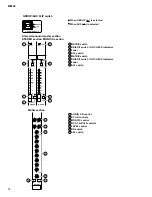
Page 10: ... G4 A10 0 G3 A9 0 G2 A8 0 G1 A7 0 AFL ON 1 2 3 4 5 7 6 GROUP AUX FLIP switch Stereo monaural master section STEREO section MONO C section Matrix section When GROUP is selected When AUX is selected MATRIX switch ON EDIT switch ON CHECK indicators Fader AFL switch MATRIX switch ON EDIT switch ON CHECK indicators Fader AFL switch 1 2 3 4 5 6 7 8 SUB IN L R control ST L R controls MONO C control G1 A7...

Page 11: ...ion Talkback oscillator section Meter select section Control section INPUT indicator MASTER indicator MASTER PFL switch L R switch LEVEL control ON switch PHONES headphone control PHONES jack 1 2 3 4 5 6 7 8 OSCILLATOR select switches OSCILLATOR ON switch MIC jack TB OSC control ON switch AUX 1 2 switch AUX 3 6 switch AUX 7 10 switch AUX 11 14 switch ST switch MONO C switch 1 2 3 4 5 6 7 8 9 10 11...

Page 12: ... jacks INPUT B jacks INPUT jacks 3 4 5 U 3 0 1 3 PEAK VU STEREO R PFL AFL R 3 0 1 3 5 7 10 20 PEAK VU 3 0 1 3 5 7 10 20 PEAK VU 3 0 1 3 5 7 10 20 PEAK VU 3 0 1 3 5 7 10 20 PEAK VU 3 0 1 3 5 7 10 20 PEAK VU 3 0 1 3 5 7 10 20 PEAK VU 3 0 1 3 5 7 10 20 PEAK MONO C STEREO L PFL AFL L 8 14 7 13 2 8 1 7 15V 15V 12V PHANTOM MASTER V 7 10 20 1 2 4 3 5 Rear panel Monaural input channel input output jacks 1...

Page 13: ...OUT L MONO C R IN OUT THRU 6 MATRIX L R 1 2 3 4 5 6 STL MONO C STR STL MONO C STR G1 A7 G2 A8 G3 A9 G4 A10 G5 A11 G6 A12 G7 A13 G8 A14 4dB 6 5 4 3 9 8 7 2 1 12 11 10 AUX OUT jacks GRP AUX OUT jacks AUX GRP OUT jacks MATRIX OUT jacks ST OUT MONO C OUT jacks MONITOR OUT jacks SUB IN MATRIX jacks SUB IN ST L R MONO C jack INSERT I O G1 A7 G8 A14 jacks INSERT I O AUX jacks INSERT I O ST L R MONO jacks...

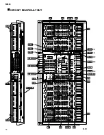
Page 14: ...OARD LAYOUT 56CH INJK STJK INJK MASOUT IN1 IN2 INPAN IN3 IN4 ST1 ST2 ST4 ST3 MASOUT1 MASOUT4 MASOUT3 CTRL 5 5 MAS1 MAS2 1 2 IN1 IN3 IN2 INPAN IN4 CTRL 3 5 CTRL 4 5 MAS4 MAS3 1 2 MASPAN MAS3 2 2 MAS2 2 2 CTRL 2 5 CTRL 1 5 ...

Page 15: ...17 M2500 1 3 3 3 2 3 3 3 2 3 1 3 2 3 1 3 METER1 METER1 METER1 METER2 1 2 METER2 1 2 METER2 1 2 METER2 2 2 METER2 2 2 ISRT 5 6 ISRT 2 6 ISRT 6 6 ISRT 1 6 ISRT 3 6 ISRT 4 6 M2500 56C ...

Reviews: