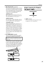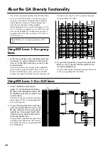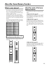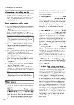
Control panel
23
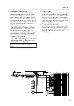
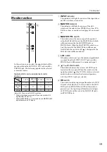
A
UTILITY switch
Press this switch to enter Utility mode, where you can
make settings for scene memories and MIDI, etc.
When you are in Utility mode (refer to page 34), the
indicator located above the switch will light.
B
RECALL switch
Use this switch to recall scenes from scene memory. If
you select a scene which has not been stored and
attempt to recall it, the MEMORY display (
3
) will
indicate “
” (No data) for approximately two sec-
onds.
C
MEMORY display
This is a three-digit LED display.
In normal mode and in check mode, it displays a
scene memory number 1–130.
In utility mode, utility-related parameters are dis-
played here (for details refer to page 34).
D
STORE key
Use this key to store a scene into scene memory. When
you press this switch once, the display will indicate
“
,” notifying you that the scene may now be
stored. At this time press the button once again to exe-
cute the Store operation. If you decide not to store the
scene, simply press any other button. Before storing a
scene memory, make sure that the Memory Protect
setting (page 34) is turned OFF.
E
CHECK switch
Use this to switch from normal mode to check mode
(refer to page 33). In check mode, the indicator
located above the switch will light.
F
0–9/ENTER buttons
Use these to numerically specify a scene memory
number. Use the 0–9 switches to enter a value, and
press the ENTER button to finalize that value.
G
▲
/
▼
switches
Use these to step through scene memory numbers
consecutively. However, the read-only scenes in mem-
ory numbers 129/130 cannot be selected by these
switches, and must be selected using the 0–9/ENTER
buttons (
6
).
These switches are also used to select parameters in
Utility mode. However in Utility mode when the oP
(recall operation) parameter is set to “
,” scenes in
memory numbers 1–8 cannot be selected by these
switches, and must be selected using the 0–9/ENTER
buttons.
If either switch is held for longer than one second, the
value will change rapidly. (For details on parameter
content, refer to page 34.)
H
DIRECT RECALL 1–8 switches
The DIRECT RECALL 1–8 switches can be used in
one of two ways, depending on the Utility mode set-
ting. With the factory settings, they will function as
“direct recall” switches that will select the scenes of
memory numbers 1–8 at a single touch. By modifying
the Utility mode settings, you can also use these as
“mute group” switches that will simultaneously select
or defeat the mute (off) settings saved in memory
numbers 1–8. (For details on direct recall and mute
groups, refer to page 36.)
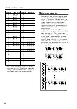
This will light if the
display number
contains no data. If
all memories contain
no data, this dot will
light when the M3000
is powered-on.
This will light when
bulk data is being
received from the
MIDI IN connector.
In normal mode, this
will light when you have
modified the settings of
the last-recalled scene.
In check mode, this will
light when you have
modified the settings of
the selected scene.
Concerning the decimal point display
Note:
Even if you press a DIRECT RECALL switch,
the scene will not change if no data has been saved
in the corresponding memory number. If this
occurs, the MEMORY display will indicate “
”
(No Data) for several seconds.
Note:
Be aware that if you press a DIRECT RECALL
switch in check mode, check mode will be forced
off, and the scene will recalled.

