background image

30

About the GA Diversity functionality

The GA Diversity functionality of the M3000A allows 
you to switch the MIX buses 1–8 between acting as 
group buses (output level from the input channels 
will be fixed) or acting as AUX buses (output level 
from the input channels will be variable).
This functionality lets you use MIX bus pairs 1/2, 3/4, 
5/6, or 7/8 either as group buses or as AUX buses, and 
gives you the flexibility to configure the console as 8 
group buses/8 AUX sends, 4 group/12 AUX send, or 
16 AUX send, etc.

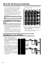
Using MIX buses 1–8 as group 
buses

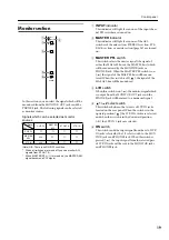
1. Of the four switches in the variable/fix select sec-

tion (page 13), set the switches to the FIX posi-
tion (

) for the MIX buses that you wish to use 

as group buses.

From top to bottom, the switches of the variable/fix 
select section correspond to MIX buses 1/2, 3/4, 5/6, 
and 7/8. For MIX buses whose switch is in the FIX 
position, the output level from the input channels will 

be fixed. At this time, M1–M8 controls of the input 
channels will have no effect.

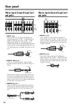
2. To send the signal from an input channel to that 

MIX bus, turn on the M1–M8 ON switch for the 
corresponding MIX bus.

The post-fader signal of the input channel will be sent 
to the corresponding MIX bus (FIX).

Using MIX buses 1–8 as AUX buses

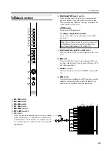
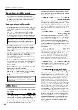
1. In the variable/fix select section 

(page 13), set the desired switch(es) 
M1–M4 to the VARIABLE position (

for the MIX buses that you wish to use 
as AUX buses.

With this setting, the output level from the 
input channels to the corresponding MIX 
bus can be adjusted.

2. To send the signal from the input chan-

nel to the desired MIX bus, turn on the 
M1–M8 ON switch for the correspond-
ing MIX bus. Then adjust the M1–M8 
control(s) for the desired mix bus(es) 
to the appropriate level.

The post-fader signal from the input chan-
nel will pass through the M1–M8 controls, 
and will be sent to the corresponding MIX 
bus (VARIABLE).

Note: 

MIX buses 9–16 always function as AUX 

buses.

+15

–15

10

0

10

0

10

0

10

0

10

0

EQ

PRE

PRE

M1

M2

M3

M4

M5

10

0

M6

10

0

M7

10

0

M8

VARIABLE
FIX

+15

–15

10

0

10

0

10

0

10

0

10

0

EQ

PRE

PRE

M1

M2

M3

M4

M5

10

0

M6

10

0

M7

10

0

M8

+15

–15

10

0

10

0

10

0

10

0

10

0

EQ

PRE

PRE

M1

M2

M3

M4

M5

10

0

M6

10

0

M7

10

0

M8

+15

–15

10

0

10

0

10

0

10

0

10

0

EQ

PRE

PRE

M1

M2

M3

M4

M5

10

0

M6

10

0

M7

10

0

M8

from INPUT

ON/EDIT

to Meter

to Meter

VARIABLE

FIX

M1–2

TO MATRIX

PAN

TO STEREO

to MAS AFL L
to MAS AFL R

to MAS PFL L
to MAS PFL R

to AFL ON

to AFL ON

to MAS PFL L
to MAS PFL R

to MAS AFL L
to MAS AFL R

ON/EDIT

MIX OUT 9

MIX OUT 1

TO STEREO

PAN

TO MATRIX

MIX
INSERT
I/O

ST

L R

MIX

(FIX)

MIX

(VARIABLE)

MIX
INSERT
I/O

1

3

5

7

1 2 3 4 5 6 7 8

2

4

6

8

9

11

13

15

10

12

14

16

AFL

AFL

Summary of Contents for M3000A

Page 1: ...Owner s Manual Mode d emploi Bedienungsanleitung M MIXING CONSOLE ...

Page 2: ...ollowing measures Relocate either this product or the device that is being affected by the interference Utilize power outlets that are on different branch circuit breaker or fuse circuits or install AC line filter s In the case of radio or TV interference relocate reorient the antenna If the antenna lead in is 300 ohm ribbon lead change the lead in to coaxial type cable If these corrective measure...

Page 3: ...put connector for illumination power supply 29 About the GA Diversity functionality 30 Using MIX buses 1 8 as group buses 30 Using MIX buses 1 8 as AUX buses 30 About the Scene Memory function 31 What is scene memory 31 About the modes of the Scene Memory function 31 Operations in normal mode 32 Operations in check mode 33 Operations in utility mode 34 Utility items 34 Control change table 35 Usin...

Page 4: ...e the mixer are a fire and electrical shock hazard Do not try to modify the mixer This could be a fire and electrical shock hazard The mixer operating temperature is between 5 C and 35 C 41 F and 95 F Turn off all audio devices and speakers when connecting to the mixer Refer to the owner s manual for each device Use the correct cables and connect as specified If you notice any abnormality such as ...

Page 5: ...ight VCA master faders allow the gain of multiple input channels to be controlled as a group By group ing the desired input channels and assigning them to a VCA master fader you can adjust the mix as appropri ate for the on state action using the VCA master fad ers alone The mono input channels provide a 26 dB pad HPF phase switch four band parametric EQ and 100 mm full stroke faders as well as DI...

Page 6: ...pass filter control This controls the cutoff frequency of the high pass fil ter The range is 20Hz 400Hz F HPF switch This switch turns the high pass filter on off When the switch is pressed the high pass filter is on and the signal component below the frequency specified by the HPF control 5 will be attenuated by 12 dB oct G EQ control This is a four band equalizer which can boost cut each band ov...

Page 7: ...ween pre post fader O M13 M14 M15 M16 pan controls These controls set the panning of the signals that are sent from the input channel to MIX buses 13 14 or MIX buses 15 16 When the control is in the center position an equal amount of signal will be sent to both buses P PRE switches These are pre fader post fader switches for the signals that are sent from the input channel to MIX buses 1 16 Pre po...

Page 8: ...the on off status of each channel stored in a scene before you actually recall the scene This is convenient when you wish to verify the status of each channel before you recall a scene In check mode you can also use the ON EDIT switches to change only the lit dark status of the CHECK indicators The actual on off setting will not be affected Use this when you wish to maintain the current mix settin...

Page 9: ...hannel fader V V Channel fader This fader adjusts the signal output level of the input channel This fader will affect the level of the signal that is sent to the ST bus and to the MIX buses if the PRE switch is off If one or more VCA groups are selected by the VCA GROUP select switches U the signal output level of that channel will also be affected by the corresponding VCA master fader s W PFL pre...

Page 10: ...T A jack can be used When the switch is in the downward position the INPUT B jacks can be used D EQ controls This is a four band equalizer which allows 15 dB of boost cut for each band The HI MID and LOW MID bands allow you to switch between two settings of Q steepness The center frequency Q values and gain range for each band is as follows E EQ switch This switches the equalizer on off The equali...

Page 11: ...14 and M15 and M16 are stereo pairs and the output level of each pair is controlled by one knob Use the PRE switch P to switch between pre post fader L M13 M14 M15 M16 BAL balance controls These controls set the left right balance of the signals that are sent from the stereo input channel to MIX buses 13 14 or MIX buses 15 16 M PRE switches These are pre fader post fader switches for the signals t...

Page 12: ...is will light when the sum of the L and R signals reaches 10 dB below the nominal level R VCA GROUP select switches These switches select the VCA master fader s which will control the signal output level of this stereo input channel When you select a VCA group 1 8 the indi cator located at the left of each switch will light and the corresponding VCA master fader VCA master section 3 will control t...

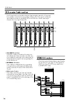
Page 13: ...ect When VARIABLE is selected The corresponding pair of MIX buses 1 2 3 4 5 6 7 8 will function as an AUX bus and the signal of the MIX VARIABLE bus will be output to the corre sponding mix channel In this case the mix level con trols M1 M8 mono input channels J stereo input channels 7 will take effect just as they are set 15 15 10 0 10 0 10 0 10 0 10 0 EQ PRE PRE M1 M2 M3 M4 M5 10 0 M6 10 0 M7 10...

Page 14: ...ode refer to page 33 E Mix master faders These faders adjust the output level of MIX OUT 1 16 These faders affect the signal which is sent to the MIX OUT 1 16 jacks the MAS AFL bus the ST bus and the matrix F AFL after fader listen switches These switches allow the signals from MIX OUT to be monitored from the MONITOR OUT jacks or PHONES jack When these switches are on the indicator will light and...

Page 15: ...ON MAS AFL MAS MIX TO MATRIX ST R L L R MIX FIX MIX VARIABLE 1 3 5 7 1 2 3 4 5 6 7 8 2 4 6 8 9 11 13 15 10 12 14 16 1 3 5 7 2 4 6 8 9 11 13 15 10 12 14 16 L R L R from ST CH from Ctrl Master ON EDIT CHECK ON CONTROL MIX 10 11 12 Same as MIX 9 to Meter TO MATRIX PAN TO STEREO AFL MIX OUT 9 MIX INSERT I O SUB ST AFL PFL L R ON MAS AFL MAS MIX TO MATRIX ST R L L R MIX FIX MIX VARIABLE 1 3 5 7 1 2 3 4...
Page 16: ...orresponding VCA group If you wish to use the VCA master faders make sure that the rear panel VCA MASTER SLAVE select switch page 28 is set to the MASTER position STEREO A section This section controls the signal that is output from the rear panel ST OUT jacks page 27 The signal level which is sent from ST OUT A to the matrix is also controlled by this section MIX 13 14 MIX 11 12 MIX 15 16 NOMINAL...

Page 17: ...itch This switch allows the ST OUT A signal which is sent to the ST OUT A jacks or to the matrix to be moni tored from the MONITOR OUT jacks or from the PHONES jack When this switch is on the indi cator will light and the pre fader signal will be sent to the MAS PFL bus and the post fader signal will be sent to the MAS AFL bus allowing you to monitor them from the MONITOR OUT jacks or the PHONES j...

Page 18: ...jack When this switch is on the indicator will light and the signal before passing through the LEVEL control will be sent to the MAS PFL bus and the signal after passing through the LEVEL control will be sent to the MAS AFL bus and can be monitored from the MONITOR OUT jacks or the PHONES jack If the master section MASTER PFL switch page 19 is off the MAS AFL bus signal can be monitored If this sw...

Page 19: ...ich will be monitored by the MONITOR jacks or PHONES jack When the MASTER PFL switch is on the signal of the MAS PFL bus will be moni tored When this switch is off the signal of the MAS AFL bus will be monitored D L R switch When this switch is on the monitor signal which is output from the MONITOR OUT jacks and the PHONES jack will be mixed to a monaural signal E 1 2 select switch This switches b...

Page 20: ... control This control adjusts the level of the signal which is output from the PHONES jack It does not affect the MONITOR OUT jacks J PHONES jack A set of headphones can be connected to this jack for monitoring PHONES MONITOR ON 10 0 LEVEL 10 0 G I J H to Meter ON ON EDIT CHECK ON CONTROL ON from STEREO B R CUE R STEREO B L CUE L from to Meter INPUT MASTER L R ON BA BA BA BA Phones PHONES 2TR IN 2...

Page 21: ...I OSCILLATOR OFF ON switch This is an off on switch for the oscillation of the oscil lator J MIC jack This is an XLR 3 31 input jack unbalanced for con necting a talkback mic It can be used with mics of 50 600 ohms impedance K LEVEL control This control adjusts the level of talkback or the oscilla tor L ON switch This switch turns talkback on off When this is on the indicator located above the swi...

Page 22: ...tor located at the left of the switch will light C MATRIX switch When this switch is turned on the M1 M9 MATRIX1 M8 M16 MATRIX8 meters page 25 will show the output levels of MATRIX OUT 1 8 At this time the indicator located at the left of the switch will light Control section On the M3000A on off settings for the mono stereo input channels the output channels of the mix sec tions and STEREO A OUT ...

Page 23: ...se switches and must be selected using the 0 9 ENTER buttons 6 These switches are also used to select parameters in Utility mode However in Utility mode when the oP recall operation parameter is set to scenes in memory numbers 1 8 cannot be selected by these switches and must be selected using the 0 9 ENTER buttons If either switch is held for longer than one second the value will change rapidly F...

Page 24: ...s or the PHONES jack by turning on the AFL switch 6 E LEVEL control This adjusts the final output level of the correspond ing matrix 1 8 The position is nominal level 0 dB F AFL switch This switch allows the output signal of the corre sponding matrix 1 8 to be monitored from the MONITOR OUT jacks or the PHONES jack When this switch is on the indicator will light and the signal before passing throu...

Page 25: ...ly these meters indicate the output levels of the signal which is output from the STEREO OUT B jacks However if the PFL switch of an input channel or an AFL switch in the mix section or matrix section etc has been pressed and you are monitoring the PFL bus the MAS PFL bus or the MAS AFL bus these meters will indicate the level of the signal which is being monitored Each meter has a PEAK indicator ...

Page 26: ...evel is 10 dB 30 dB To use these jacks you must set the A B select switch of the corre sponding stereo input channel to the A position Pin wiring is as follows E INPUT B jacks These are RCA phono input jacks unbalanced Nominal input level is 10 dB 20 dB To use these jacks you must set the A B select switch of the corre sponding stereo input channel to the B position Pin wiring is as follows 4 NPUT...

Page 27: ...minal output level is 4 dB Pin wiring is as follows L ST OUT A B jacks These are XLR output jacks balanced for outputting the signals from the STEREO A B sections Nominal output level is 4 dB for both sections Pin wiring is as 2 10dBV 1 4dB MASTER SLAVE VCA MASTER SLAVE VCA EXTERNAL I O CUE CONTROL IN OUT THRU MIDI 2TR IN MONITOR OUT 4dB MATRIX OUT 4dB MIX OUT 4dB ST INSERT I O 0dB MATRIX SUB IN 4...

Page 28: ...nected to be controlled from a single console If the M3000A is to be the mas ter for the VCA control set the VCA MASTER SLAVE switch N to the MASTER position If the M3000A is to be the slave set the VCA MASTER SLAVE switch to the SLAVE position Pin wiring is as follows S VCA MASTER SLAVE switch When an external device with VCA control function ality is connected to the VCA EXTERNAL I O connec tor ...

Page 29: ...o the MIDI IN connector of the third unit With these connec tions selecting a scene on the first M3000A will cause the scene to change on the second and third units in the same way V DC POWER INPUT connector Connect the included PW3000MA power supply to this connector to supply power to the M3000A It is also possible to connect two PW3000MA units in parallel as shown in the following diagram In th...

Page 30: ...ng MIX buses 1 8 as AUX buses 1 In the variable fix select section page 13 set the desired switch es M1 M4 to the VARIABLE position for the MIX buses that you wish to use as AUX buses With this setting the output level from the input channels to the corresponding MIX bus can be adjusted 2 To send the signal from the input chan nel to the desired MIX bus turn on the M1 M8 ON switch for the correspo...

Page 31: ...de the CHECK switch and UTILITY switch indicators of the control section will be dark Check mode refer to page 33 In this mode you can confirm the settings of a scene before you actually recall it or edit the on off settings of each input channel or mix bus before storing a scene When the M3000A is in Check mode the indi cator of the CHECK switch in the control section will light Utility mode refe...

Page 32: ...led 3 To instantly recall a memory number 1 8 press the desired DIRECT RECALL 1 8 switch With the factory settings the scenes of memory num bers 1 8 can be recalled directly by the DIRECT RECALL 1 8 switches This is referred to as direct recall In this case it is not necessary to press the RECALL switch and the scene will change instantly If you press the switches following a direct recall operati...

Page 33: ...maintaining the current on off settings 1 When the M3000A is in normal mode press the control section CHECK switch The CHECK switch LED will light and the M3000A will enter check mode 2 Use the switches of the control section or the 0 9 ENTER buttons to make the MEMORY display indicate the scene number for the desired storing destination If you press a 0 9 button to change the number it will be co...

Page 34: ... an external MIDI device the contents of memory will not be rewritten recall operation dir GrP Factory setting dir This changes the operation of the DIRECT RECALL 1 8 switches When this is set to the DIRECT RECALL 1 8 switches will function as direct recall switches which directly recall memory numbers 1 8 When this is set to the DIRECT RECALL 1 8 switches will function as mute group switches to a...

Page 35: ...smits a request for a bulk dump from the MIDI OUT connector If the respective MIDI IN OUT connectors of two M3000A units are connected such a request will cause all scene memo ries ALL or the specified scene memory 1 128 of the other M3000A to overwrite the scene memory or memories of this M3000A After selecting or press the STORE switch to transmit the bulk dump request MIDI message Control chang...

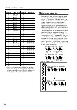
Page 36: ... muted off in any of the mute groups will be muted Control No ON EDIT Switch Control No ON EDIT Switch 60 CH INPUT 56 90 61 MIX 1 OUT 91 62 MIX 2 OUT 92 63 MIX 3 OUT 93 64 MIX 4 OUT 94 65 MIX 5 OUT 95 66 MIX 6 OUT 96 67 MIX 7 OUT 97 68 MIX 8 OUT 98 69 STEREO A OUT 99 70 100 71 101 72 102 73 MIX 9 OUT 103 74 MIX 10 OUT 104 75 MIX 11 OUT 105 MUTE GROUP 1 76 MIX 12 OUT 106 MUTE GROUP 2 77 MIX 13 14 O...

Page 37: ...N EDIT switch of each input channel or mix channel will function like a conventional ON OFF mute switch However the MEMORY display will go dark and the switches for the Scene Memory func tionality cannot be operated Mute group 1 scene memory number 1 MUTE OFF ON ON MUTE OFF ON Mute group 3 scene memory number 3 ON ON ON MUTE OFF MUTE OFF ON EDIT CHECK ON ON EDIT CHECK ON ON EDIT CHECK ON ON EDIT C...

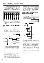
Page 38: ...er fader to control multiple channels If two or more channels are assigned to the same VCA group you can use a single VCA master fader to con trol them The following diagram shows an example of the signal flow when VCA GROUP select switch 1 is turned on for input channels 1 5 and 16 If two or more input channels are assigned to a VCA group the gain of each channel can be controlled both by the cha...

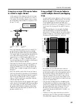
Page 39: ... the same inputs at different levels as the on stage performance progresses In such situations you can assign multiple input channels to multiple VCA groups this is referred to as overlapping VCA and control most levels using only the eight VCA master faders The following diagram is an example of multiple input channels being controlled by multiple VCA master faders VCA master fader 1 controls the...

Page 40: ...CA group will be muted This is convenient when you wish to simultaneously mute or un mute multiple channels without operating the faders By using this in conjunction with the Scene Memory function you can also mute only specific inputs within a VCA group In the above example if you recall a scene in which chorus 1 3 inputs 12 14 are turned off chorus 1 3 will be muted from VCA groups 4 6 and 8 ...

Page 41: ...rror message will be displayed for several seconds if a check sum error occurs while receiv ing bulk dump MIDI data Check the MIDI connec tions and whether the transmitting device is set appropriately The internal battery voltage has fallen below 2 5V or is an abnormal value in this case the display will indicate This error message will be displayed when the power is turned on or when the Utility ...

Page 42: ...B point CH INPUT Equalization 15 15 dB maximum HIGH 1k 20 kHz peaking Q 0 667 HIGH MID 400 8 kHz peaking Q 1 41 2 88 LOW MID 80 1 6 kHz peaking Q 1 41 2 88 LOW 30 600 Hz peaking Q 0 667 ST CH INPUT Equalization 15 15 dB maximum HIGH 20 kHz peaking Q 0 667 HIGH MID 3 kHz peaking Q 1 41 2 88 LOW MID 800 Hz peaking Q 1 41 2 88 LOW 50 Hz peaking Q 0 667 Phantom Power 48V DC is applied to balanced inpu...

Page 43: ...B 24 5 mV 10 dB 245 mV XLR 3 31 type 1 10 16 dB 123 mV 10 dB 2 45 V 30 dB 24 5 V ST CH B INPUT L R 1 4 20 10 kΩ 600 Ω Lines 46 dB 3 88 mV 20 dB 77 5 mV 0 dB 0 775 V Phono Jack 3 10 16 dB 123 mV 10 dB 2 45 V 30 dB 24 5 V TALKBACK IN 10 kΩ 50 600 Ω Mics 66 dB 0 388 mV 50 dB 2 45 mV 20 dB 77 5 mV XLR 3 31 type 2 2TR IN 1 L R 2TR IN 2 L R 10 kΩ 600 Ω Lines 2 dB 0 616 V 4 dB 1 23 V 24 dB 12 3 V XLR 3 3...

Page 44: ...Pin No Signal name 1 Power supply remote 2 15 V 3 15 V GND 4 48 V GND 5 15 V 6 12 V 7 12V GND power supply remote 8 Power supply remote 9 48 V 10 FRAME GND Pin No Signal name 1 VCA GROUP 1 2 VCA GROUP 2 3 VCA GROUP 3 4 VCA GROUP 4 5 VCA GROUP 5 6 VCA GROUP 6 7 VCA GROUP 7 8 VCA GROUP 8 9 GND 3 2 1 1 2 6 7 8 9 3 4 5 10 9 8 7 6 5 4 ...

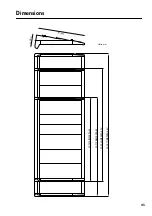
Page 45: ...45 Dimensions W 2571 M3000A 56C W 2043 M3000A 40C W 1779 M3000A 32 W 1515 M3000A 24 D 8 7 4 H 2 6 5 Units mm ...

Page 46: ... be transmitted Bulk Dump Request messages will not be echoed back bulk data will be transmitted instead 5 Bulk Out Bulk Dump Request The following bulk messages can be transmitted and received 1 SCENE MEMORY No BULK OUT FORMAT 2 SCENE MEMORY No BULK REQUEST FORMAT MIDI Control Change No ON EDIT switch Assign 1 48 CH INPUT 1 48 49 52 ST CH INPUT 1 4 53 60 CH INPUT 49 56 61 68 MIX 1 8 OUT 69 STEREO...

Page 47: ...e voice x Velocity Note ON x x Note OFF x x After Key s x x Touch Ch s x x Pitch Bend x x 1 69 o o 1 Control Change 73 78 o o 105 112 o o Program o 0 127 o 0 127 Change True 1 128 System Exclusive o o 2 Song Pos x x Common Song Sel x x Tune x x System Clock x x Real Time Commands x x Local ON OFF x x Aux All Notes OFF x x Messages Active Sense o x Reset x x Notes 1 See Control Change chart 2 Bulk ...

Reviews: