background image


PERIODIC MAINTENANCE AND MINOR REPAIR


6-13


1

2

3

4

5

6

7

8

9


necessary.


To install the spark plug


1. Measure the spark plug gap with a

wire thickness gauge and, if nec-
essary, adjust the gap to specifica-
tion.

2. Clean the surface of the spark plug

gasket and its mating surface, and
then wipe off any grime from the
spark plug threads.

3. Install the spark plug with the

spark plug wrench, and then tight-
en it to the specified torque.

NOTE:


If a torque wrench is not available when
installing a spark plug, a good estimate
of the correct torque is 1/4–1/2 turn
past finger tight. However, the spark
plug should be tightened to the speci-


fied torque as soon as possible.

4. Install the spark plug cap.

NOTE:


Make sure the spark plug wire is fas-


tened in the clamp as shown.

5. Install the spark plug cover by in-

stalling the screws.

6. Place the storage compartment

mat in the original position.

7. Close the rider seat.


Specified spark plug:

NGK/CR7E 


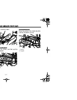
1. Spark plug gap


Spark plug gap:

0.7–0.8 mm (0.028–0.031 in) 

1


Tightening torque:


Spark plug:

12.5 Nm (1.25 m·kgf, 9 ft·lbf)


1. Spark plug cap
2. Spark plug wire clamp

1

2

Summary of Contents for MAJESTY 400

Page 1: ...5RU 28199 10 YP400T OWNER S MANUAL ...

Page 2: ......

Page 3: ... inspection and basic maintenance of this scooter If you have nance of your scooter please consult a Yamaha dealer ter fully comply with the emissions standards for clean air applicable at the ndards without reducing the performance or economy of operation of the mportant that you and your Yamaha dealer pay close attention to the rec g instructions contained within this manual ...

Page 4: ...R MOTORCYCLE RIDING TIPS BOOKLET CAREFULLY S SCOOTER DO NOT ATTEMPT TO OPERATE THIS SCOOTER UN LEDGE OF ITS CONTROLS AND OPERATING FEATURES AND UNTIL OPER RIDING TECHNIQUES REGULAR INSPECTIONS AND CARE ING SKILLS WILL ENSURE THAT YOU SAFELY ENJOY THE CAPA OTER Symbol means ATTENTION BECOME ALERT YOUR SAFETY IS WARNING instructions could result in severe injury or death to the a bystander or a pers...

Page 5: ...R S MANUAL amaha Motor Corporation U S A 1st edition June 2004 All rights reserved printing or unauthorized use ut the written permission of ha Motor Corporation U S A s expressly prohibited Printed in Japan P N LIT 11626 18 38 AFFIX DEALER LABEL HERE ...

Page 6: ...Cast wheels 6 25 Accessories and replacement parts 6 26 Front and rear brake lever free play 6 26 Adjusting the rear brake lock lever cable 6 27 Checking the front and rear brake pads 6 27 Checking the brake fluid level 6 28 Changing the brake fluid 6 29 Checking and lubricating the cables 6 29 Checking and lubricating the throttle grip and cable 6 30 Lubricating the front and rear brake levers 6 ...

Page 7: ...TABLE OF CONTENTS ...

Page 8: ...oter accidents to occur Ride where other motorists can see you Avoid riding in another motorist s blind spot Many accidents involve inexperi enced operators In fact many op erators who have been involved in accidents do not even have a cur rent driver s license Make sure that you are qualified and that you only lend your scooter to other qualified opera tors Know your skills and limits Staying wit...

Page 9: ...during or after operation ey become very hot and can use burns Always wear protec tive clothing that covers your legs ankles and feet Passengers should also observe the above precautions Modifications Modifications made to this scooter not approved by Yamaha or the removal of original equipment may render the scooter unsafe for use and may cause severe personal injury Modifications may also make y...

Page 10: ...ssories fitted to the handle ar or the front fork area can reate instability due to improper weight distribution or aerody namic changes If accessories are added to the handlebar or front fork area they must be as lightweight as possible and should be kept to a minimum Bulky or large accessories may seriously affect the stability of the scooter due to aerodynamic effects Wind may attempt to lift t...

Page 11: ...rea with soap and ter and change your clothes EAU10371 Further safe riding points Be sure to signal clearly when making turns Braking can be extremely difficult on a wet road Avoid hard braking because the scooter could slide Apply the brakes slowly when stopping on a wet surface Slow down as you approach a cor ner or turn Once you have com pleted a turn accelerate slowly Be careful when passing p...

Page 12: ...1 5 ...

Page 13: ...SAFETY INFORMATION 1 6 1 EAU10381 ly before operating this vehicle 2 1 3 5 6 7 4 ...

Page 14: ...1 7 eld 35Y A0 AD CLE ng 18K 00 5RU 21668 00 WARNING Improper loading can cause loss of control Read owner s manual for proper loading 3JJ 28446 A1 3LD 24877 A0 LOAD LIMIT 5 kg 11 lbs 4 5 6 ...

Page 15: ...SAFETY INFORMATION 1 8 1 ...

Page 16: ...2 1 EAU10410 9 2 3 5 6 7 8 4 10 11 9 Engine oil filter element page 6 14 10 Centerstand page 6 30 11 Sidestand page 3 14 6 30 ...

Page 17: ...DESCRIPTION 2 2 2 3 4 5 6 7 8 9 EAU10420 5 3 4 ...

Page 18: ...2 3 EAU10430 3 4 5 6 7 8 9 10 11 12 9 Throttle grip page 6 23 10 Front storage compartment B page 3 13 11 Main switch steering lock page 3 1 12 Front storage compartment A page 3 13 ...

Page 19: ...l the way to e left sh the key in from the OFF po on and then turn it to LOCK ile still pushing it move the key ock the steering he key in and then turn it to while still pushing it ARNING EWA10060 turn the key to OFF or K while the vehicle is moving ise the electrical systems will be switched off which may result in loss of control or an accident Make sure that the vehicle is stopped be fore turn...

Page 20: ...ircuit of the warning light checked by turning the key to the warning light does not come few seconds then go off have aha dealer check the electrical EAU11601 Speedometer The speedometer shows the riding speed When the key is turned to ON the speedometer needle will sweep once across the speed range and then return to zero in order to test the electrical cir cuit 1 Speedometer 1 ...

Page 21: ...ich shows the to tal distance traveled two tripmeters which show the distance traveled since they were last set to zero a fuel reserve tripmeter which shows the distance traveled since the bottom segment of the fuel meter and fuel level warning sym ambient temperature display ant temperature meter meter meter tripmeters ECT button ET button 1 2 3 4 5 6 1 V belt replacement indicator V BELT 2 Fuel ...

Page 22: ...ter manually it will reset itself automatically and the display will return to the prior mode af ter refueling and traveling 5 km 3 mi NOTE The display cannot be changed back to TRIP F after pushing the RESET button Fuel meter With the key in the ON position the fuel meter indicates the amount of fuel in the fuel tank The display segments of the fuel meter disappear towards E Empty as the fuel lev...

Page 23: ...LT dicator flashes every 20000 km mi when the V belt needs to be replaced The electrical circuit of the indicator can be checked according to the following procedure 1 Turn the key to ON and make sure that the engine stop switch is set to 2 If the indicator does not come on have a Yamaha dealer check the electrical circuit Self diagnosis device This model is equipped with a self diag nosis device ...

Page 24: ...e displayed he ambient temperature climbs ove 50 C 122 F a higher mperature than 50 C 122 F not be displayed e accuracy of the temperature ding may be affected when ng slowly approximately under km h 12 5 mi h or when pped at traffic signals railroad ssings etc EAU12343 Handlebar switches Left 1 Dimmer switch 2 Turn signal switch 3 Horn switch 1 2 3 ...

Page 25: ...when the vehicle overturns n the throttle cable is stuck EAU12720 witch e sidestand up push this switch pplying the front or rear brake to he engine with the starter ION ECA10050 age 5 1 for starting instruc rior to starting the engine EAU12900 Front brake lever The front brake lever is located on the right handlebar grip To apply the front brake pull this lever toward the handle bar grip 1 Front ...

Page 26: ...al position sure to check that the rear eel does not move when the r brake lock lever is applied provide secure locking of the rear wheel apply the rear brake le ver first before moving the rear brake lock lever to the left WARNING EWA12361 Never move the rear brake lock lever to the left while the vehicle is mov ing otherwise loss of control or an accident may result Make sure that the vehicle is...

Page 27: ...arks insert the el tank cap into the tank opening d then push down on the cap rn the key counterclockwise to e original position and then re move it 3 Close the lid WARNING EWA11120 Be sure that the fuel tank cap is properly installed and locked before riding the scooter ank cap h marks 1 1 ...

Page 28: ... higher If g or pinging occurs use a e of a different brand or premi aded fuel Use of unleaded fuel end spark plug life and reduce ance costs Gasohol There are two types of gasohol gaso hol containing ethanol and that contain ing methanol Gasohol containing ethanol can be used if the ethanol con tent does not exceed 10 Gasohol containing methanol is not recom mended by Yamaha because it can cause ...

Page 29: ...7 8 9 EAU34140 seat n the rider seat ace the scooter on the center and sert the key into the main switch d then turn it counterclockwise NOTE Do not push inward when turning the key 3 Fold the rider seat up seat enger seat 2 1 1 Open 1 Rider seat 1 1 ...

Page 30: ...er seat he original position and then in l the bolt se the rider seat ure that the passenger seat is y secured before riding EAU34150 Adjusting the rider seat The rider seat can be adjusted as fol lows to change the riding position 1 Open the rider seat See page 3 11 2 Remove the bolts nger seat holder 2 2 1 Rider seat 1 ...

Page 31: ...clockwise and then he lock while pushing the button en the storage compartment t is unlocked simply grasp the hile pushing the button in the storage compartment push into the original position insert y in the lock turn it clockwise en remove it Front storage compartment B To open the storage compartment slide the lever up and then pull on the lever n 2 3 1 1 Lock 2 Lid 2 1 ...

Page 32: ... built in sidestand switch is part of the ignition circuit cut off system which cuts the ignition in certain situations See further down for an explanation of the ignition circuit cut off system WARNING EWA10240 The vehicle must not be ridden with the sidestand down or if the side stand cannot be properly moved up or does not stay up otherwise the sidestand could contact the ground and distract th...

Page 33: ...ollowing func prevents starting when the side and is up but neither brake is ap ed prevents starting when either ake is applied but the sidestand still down uts the running engine when the estand is moved down cally check the operation of the circuit cut off system according ollowing procedure ARNING EWA10250 alfunction is noted have a a dealer check the system be ding ...

Page 34: ... switch may be defective The scooter should not be ridden until checked by a Yamaha dealer The brake switch may be defective The scooter should not be ridden until checked by a Yamaha dealer The sidestand switch may be defective The scooter should not be ridden until checked by a Yamaha dealer NOTE ...

Page 35: ...as a result of exposure to the elements Any damage fluid leakage or loss ces Therefore it is very important in addition to a thorough visual inspec e he vehicle is used Such an inspection can be accomplished in a very short n worth the time involved EWA11150 ot working properly have it inspected and repaired before operating ...

Page 36: ...el m for leakage 6 18 ve Yamaha dealer bleed hydraulic system or wear y eservoir commended brake fluid to specified level tem for leakage 6 27 6 28 ve Yamaha dealer bleed hydraulic system or wear y eservoir commended brake fluid to specified level tem for leakage 6 27 6 28 ation is smooth ay amaha dealer adjust cable free play and lubricate cable 6 23 6 30 ...

Page 37: ... n and tread depth y 6 23 6 25 ration is smooth ting points if necessary 6 30 ration is smooth ecessary 6 30 nuts bolts and screws are properly tightened y y ignition circuit cut off system e have Yamaha dealer check vehicle 3 14 CHECKS PAGE ...

Page 38: ... on page 3 15 ver ride with the sidestand wn n the key to ON and make e that the engine stop switch is to se the throttle completely rt the engine by pushing the rt switch while applying the front ear brake NOTE If the engine does not start release the start switch wait a few seconds and then try again Each starting attempt should be as short as possible to pre serve the battery Do not crank the e...

Page 39: ... can be adjusted by opening sing the throttle To increase the turn the throttle grip in direction reduce the speed turn the throt in direction b EAU16791 Braking 1 Close the throttle completely 2 Apply both front and rear brakes simultaneously while gradually in creasing the pressure Front a b ...

Page 40: ...new do not put an excessive load on it for the first 1600 km 1000 mi The various parts in the engine wear and polish themselves to the correct operating clearances During this period prolonged full throt tle operation or any condition that might result in engine overheating must be avoided EAU34320 0 1000 km 0 600 mi Avoid prolonged operation above 4000 r min 1000 1600 km 600 1000 mi Avoid prolong...

Page 41: ...from the main ARNING EWA10310 nce the engine and exhaust stem can become very hot rk in a place where pedestri s or children are not likely to uch them o not park on a slope or on soft ound otherwise the vehicle ay overturn ION ECA10380 park in an area where there e hazards such as grass or lammable materials ...

Page 42: ... ARE THE MAINTE NANCE SERVICES RELATED TO EMISSIONS CONTROL THESE CONTROLS NOT ONLY FUNCTION TO ENSURE CLEANER AIR BUT ARE ALSO VITAL TO PROPER EN GINE OPERATION AND MAXIMUM PERFORMANCE IN THE FOLLOW ING PERIODIC MAINTENANCE CHARTS THE SERVICES RELATED TO EMISSIONS CONTROL ARE GROUPED SEPARATELY THESE SERVICES REQUIRE SPECIALIZED DATA KNOWLEDGE AND EQUIP MENT YAMAHA DEALERS ARE TRAINED AND EQUIPPE...

Page 43: ...6 7 8 9 do not have the tools or experi equired for a particular job have aha dealer perform it for you ARNING EWA10350 cations not approved by a may cause loss of perfor and render the vehicle un or use Consult a Yamaha before attempting any chang ...

Page 44: ...m the service INITIAL ODOMETER READINGS 600 mi 1000 km or 1 month 4000 mi 7000 km or 6 months 8000 mi 13000 km or 12 months 12000 mi 19000 km or 18 months 16000 mi 25000 km or 24 months 20000 mi 31000 km or 30 months cks or s Replace clear d Every 26600 mi 42000 km d r dam ve dam arts ...

Page 45: ...AL ODOMETER READINGS 600 mi 1000 km or 1 month 4000 mi 7000 km or 6 months 8000 mi 13000 km or 12 months 12000 mi 19000 km or 18 months 16000 mi 25000 km or 24 months 20000 mi 31000 km or 30 months Every 12000 mi 19000 km evel eces evel eces mage Every 4 years amage for ooth ...

Page 46: ...When the oil change indicator flashes every 3000 mi 5000 km cle for Every 3000 mi 5000 km INITIAL ODOMETER READINGS 600 mi 1000 km or 1 month 4000 mi 7000 km or 6 months 8000 mi 13000 km or 12 months 12000 mi 19000 km or 18 months 16000 mi 25000 km or 24 months 20000 mi 31000 km or 30 months ...

Page 47: ...ting from 8000 mi 13000 km or 12 months Every 12500 mi 20000 km d vehi Every 3 years kage Every 12500 mi 20000 km ee play free ip INITIAL ODOMETER READINGS 600 mi 1000 km or 1 month 4000 mi 7000 km or 6 months 8000 mi 13000 km or 12 months 12000 mi 19000 km or 18 months 16000 mi 25000 km or 24 months 20000 mi 31000 km or 30 months ...

Page 48: ...ent service if you are riding in unusually wet or dusty areas ders and calipers always change the fluid Regularly check the brake fluid onents of the brake master cylinders and calipers and change the brake and if cracked or damaged ...

Page 49: ...r en pulling the fastener out To install the cowling 1 Place the cowling in the original position and then install the quick fasteners NOTE To install the quick fastener push the center pin out so that it will protrude from the fastener head insert the fas tener into the cowling and then push the protruding pin in until it is flush with the fastener head 2 Close the rider seat Cowling B To remove ...

Page 50: ...ge 3 11 move the grab bar by removing grab bar bolts and collars move the screw access cover pulling it off 5 Remove the screws and then pull the cowling off To install the cowling 1 Place the cowling in the original position and then install the screws bar bolt bar 4 3 2 1 Screw access cover 1 Screw 1 1 1 ...

Page 51: ...ews ll the cowling down slightly and en pull it outward as shown To install the cowling 1 Insert the tabs on the cowling into the slots as shown and then install the screws 2 Place the left floorboard mats in the original position oorboard mat w 1 4 1 Cowling E 1 Tab 1 1 13 1 ...

Page 52: ...NOR REPAIR 6 11 n install the bolts B ove the panel e the screws and then pull the utward To install the panel Place the panel in the original position and then install the screws B 2 1 1 Screw 2 Panel B 1 2 ...

Page 53: ... the spark plug is a medium to light tan the ideal color when the vehicle is ridden normally NOTE If the spark plug shows a distinctly dif ferent color the engine could be defec tive Do not attempt to diagnose such problems yourself Instead have a Yamaha dealer check the vehicle 2 Check the spark plug for electrode erosion and excessive carbon or other deposits and replace it if ge compartment mat...

Page 54: ... turn ger tight However the spark ould be tightened to the speci ue as soon as possible tall the spark plug cap ure the spark plug wire is fas the clamp as shown 5 Install the spark plug cover by in stalling the screws 6 Place the storage compartment mat in the original position 7 Close the rider seat ening torque ark plug 12 5 Nm 1 25 m kgf 9 ft lbf 1 Spark plug cap 2 Spark plug wire clamp 1 2 ...

Page 55: ...e can result in a ading art the engine warm it up for veral minutes and then turn it ait a few minutes until the oil set s remove the oil filler cap wipe e dipstick clean insert it back o the oil filler hole without rewing it in and then remove it again to check the oil level NOTE The engine oil should be between the minimum and maximum level marks 4 If the engine oil is below the mini mum level m...

Page 56: ...15 ps 5 7 if the oil filter element is g replaced move the oil filter element cover removing the bolts 6 Remove and replace the oil filter element and O rings e oil drain bolt er 2 1 Bolt 2 Oil filter element cover 2 1 3 ...

Page 57: ...ING II or higher Be sure no foreign material en ters the crankcase 10 Start the engine and then let it idle for several minutes while checking it for oil leakage If oil is leaking im mediately turn the engine off and check for the cause 11 Reset the oil change indicator ac cording to the following procedure To reset the oil change indicator 1 Turn the key to ON tening torque filter element cover b...

Page 58: ...epair the scooter In addition the final transmis sion oil must be changed as follows at the intervals specified in the periodic maintenance and lubrication chart 1 Start the engine warm it up by riding the scooter for several min utes and then stop the engine 2 Place the scooter on the center stand 3 Place an oil pan under the final transmission case to collect the used oil 4 Remove the oil filler...

Page 59: ...h ride In addition the cool ant must be changed at the intervals specified in the periodic maintenance and lubrication chart EAU34191 To check the coolant level 1 Place the vehicle on a level sur face and hold it in an upright posi tion NOTE The coolant level must be checked on a cold engine since the level varies with engine temperature Make sure that the vehicle is posi tioned straight up when c...

Page 60: ...lace it with cool ant as soon as possible other wise the engine may not be sufficiently cooled and the cool ing system will not be protected against frost and corrosion If water has been added to the coolant have a Yamaha dealer check the antifreeze content of the coolant as soon as possible otherwise the effectiveness of the coolant will be reduced WARNING EWA10380 Never attempt to remove the rad...

Page 61: ...ance and lubrication Service all air filter elements equently if you are riding in un wet or dusty areas cing the air filter elements ace the scooter on the center and ue as follows for each air filter el move the air filter case cover by moving the rubber cap and rews Left Right 3 Pull the air filter element out 1 Screw 2 Air filter case cover 3 Rubber cap 1 Screw 2 Air filter case cover 3 Rubber...

Page 62: ...e engine may re t e engine should never be op ted without the filter ele nts installed otherwise the ton s and or cylinder s may come excessively worn n the air filter check hoses eck the hose at the bottom of h air filter cases for accumulat dirt or water Left Right 2 If dirt or water is visible remove the hose clean it and then install it 1 Air filter check hose 1 Air filter check hose 1 1 ...

Page 63: ...n eck the V belt case air filter ele ent for damage and replace it if necessary 7 Install the V belt case air filter ele ment by installing the screws 8 Install the V belt air filter case cov er by installing the screws CAUTION ECA12940 Make sure that the V belt filter ele ment is properly seated in its case 9 Install the panel 10 Install the cowling w t case air filter element 2 1 ...

Page 64: ...l ity and safe operation of your vehicle note the following points regarding the specified tires Tire air pressure The tire air pressure should be checked and if necessary adjusted before each ride WARNING EWA10500 The tire air pressure must be checked and adjusted on cold tires i e when the temperature of the tires equals the ambient temperature The tire air pressure must be ad justed in accordan...

Page 65: ...ewall is cracked have a Yamaha dealer replace the tire immediately NOTE The tire tread depth limits may differ from country to country Always comply with the local regulations Tire information This model is equipped with tubeless tires WARNING EWA10590 Operating the scooter with exces sively worn tires decrease riding stability and can lead to loss of con trol Have excessively worn tires re placed...

Page 66: ... eel must be replaced e wheel should be balanced enever either the tire or wheel s been changed or replaced An balanced wheel can result in or performance adverse han g characteristics and a short ed tire life e at moderate speeds after anging a tire since the tire sur e must first be broken in for it develop its optimal characteris er repairing or replacing the rear tire tighten the valve stem nu...

Page 67: ...6 2 3 4 5 6 7 8 9 e of items which have not pproved by Yamaha EAU33451 Front and rear brake lever free play Front Rear There should be no free play at the brake lever ends If there is free play have a Yamaha dealer inspect the brake system ...

Page 68: ...e pads The front and rear brake pads must be checked for wear at the intervals spec ified in the periodic maintenance and lubrication chart EAU22420 Front brake pads Each front brake pad is provided with a wear indicator groove which allows you to check the brake pad wear with out having to disassemble the brake To check the brake pad wear check the wear indicator groove If a brake pad has worn to...

Page 69: ...low be sure to check the brake pads for wear and the brake system for leakage Observe these precautions When checking the fluid level make sure that the top of the brake fluid reservoir is level Use only the recommended quality brake fluid otherwise the rubber seals may deteriorate causing leakage and poor braking perfor mance Refill with the same type of brake fluid Mixing fluids may result in a ...

Page 70: ...king and lubricating the cables The operation of all control cables and the condition of the cables should be checked before each ride and the ca bles and cable ends should be lubricat ed if necessary If a cable is damaged or does not move smoothly have a Yamaha dealer check or replace it WARNING EWA10710 Damage to the outer housing of ca bles may result in internal rusting and cause interference ...

Page 71: ...t the s specified in the periodic main e and lubrication chart EAU23210 Checking and lubricating the centerstand and sidestand The operation of the centerstand and sidestand should be checked before each ride and the pivots and met al to metal contact surfaces should be lubricated if necessary ecommended lubricant Lithium soap based grease all purpose grease ...

Page 72: ... so that no danger of it falling over the inner tubes for scratches e and excessive oil leakage ck the operation ce the vehicle on a level sur e and hold it in an upright posi n ile applying the front brake sh down hard on the handlebars eral times to check if the front k compresses and rebounds oothly CAUTION ECA10590 If any damage is found or the front fork does not operate smoothly have a Yamah...

Page 73: ...king the wheel bearings The front and rear wheel bearings must be checked at the intervals specified in the periodic maintenance and lubrica tion chart If there is play in the wheel hub or if the wheel does not turn smoothly have a Yamaha dealer check the wheel bearings ...

Page 74: ...ind that the ends to discharge more quickly if the vehicle is equipped with optional electrical accessories To store the battery 1 If the vehicle will not be used for more than one month remove the battery fully charge it and then place it in a cool dry place 2 If the battery will be stored for more than two months check it at least once a month and fully charge it if necessary 3 Fully charge the ...

Page 75: ...ind cowling A age 6 8 e is blown replace it as follows rn the key to OFF and turn off e electrical circuit in question move the blown fuse and then tall a new fuse of the specified mperage main fuse is blown remove the ar to access the main fuse After ng the main fuse install the grab ee page 6 8 1 Spare main fuse 2 Main fuse 1 Fuse box 2 Taillight fuse 1 2 1 2 ...

Page 76: ...he key to ON and turn on electrical circuit in question to eck if the device operates the fuse immediately blows ain have a Yamaha dealer check the electrical system fied fuses in fuse 40 0 A ition fuse 10 0 A naling system fuse 10 0 A adlight fuse 20 0 A llight fuse 10 0 A diator fan fuse 10 0 A ctronic fuel injection fuse 10 0 A ckup fuse 10 0 A ...

Page 77: ...ght ail brake light does not come on Yamaha dealer check it EAU36121 Replacing a front turn signal light bulb 1 Place the scooter on the center stand 2 Remove panel A See page 6 8 3 Remove the windshield by remov ing the screws 4 Remove the front turn signal light unit by removing the screws 1 Screw 2 Windshield 1 6 2 ...

Page 78: ...he windshield by installing screws tall panel A EAU34260 Replacing a rear turn signal light bulb 1 Place the scooter on the center stand 2 Remove cowling C for replacing the left turn signal light bulb or cowling D for replacing the right turn signal light bulb See page 6 8 3 Remove the socket together with the turn signal light bulb by turning it counterclockwise 4 Remove the defective bulb by pu...

Page 79: ...te light lens by moving the screws move the defective bulb by shing it in and turning it counter ckwise 4 Insert a new bulb into the socket push it in and then turn it clock wise until it stops 5 Install the license plate light lens and license plate light cover by in stalling the screws 6 Install the cowling se plate light lens se plate light cover w 1 2 3 1 Bulb 1 ...

Page 80: ...ND MINOR REPAIR 6 39 ...

Page 81: ...on Check the ignition Have a Yamaha dealer check the vehicle dry cloth and correct the or replace the spark plug a dealer check the vehicle The engine does not start Have a Yamaha dealer check the vehicle The engine does not start Check the battery The battery is good Check the battery lead connections and charge the battery if necessary Open the throttle halfway and operate the electric starter ...

Page 82: ... to escape When the hissing p while turning it counterclockwise and then remove the cap arily used instead provided that it is changed to the recommended coolant The coolant level is OK The coolant level is low Check the cooling system for leakage Have a Yamaha dealer check and repair the cooling system Add coolant See NOTE Start the engine If the engine overheats again have a Yamaha dealer check ...

Page 83: ...ical oducts on plastic parts Be re to avoid using cloths or onges which have been in contact with strong or abrasive cleaning products solvent or thinner fuel gasoline rust re movers or inhibitors brake flu id antifreeze or electrolyte Do not use high pressure wash ers or steam jet cleaners since they cause water seepage and deterioration in the following ar eas seals of wheel and swing arm bearin...

Page 84: ...all metal uding chrome and nickel plat surfaces e spray oil as a universal clean er to remove any remaining dirt 5 Touch up minor paint damage caused by stones etc 6 Wax all painted surfaces 7 Let the scooter dry completely be fore storing or covering it WARNING EWA10940 Make sure that there is no oil or wax on the brakes or tires If necessary clean the brake discs and brake linings with a regular...

Page 85: ...will event fuel deposits from building Pour the drained fuel into the fuel tank 3 Fill up the fuel tank and add fuel stabilizer if available to prevent the fuel tank from rusting and the fuel from deteriorating 4 Perform the following steps to pro tect the cylinder piston rings etc from corrosion a Remove the spark plug cap and spark plug b Pour a teaspoonful of engine oil into the spark plug bore...

Page 86: ...AGE 7 4 ss than 0 C 30 F or more n 30 C 90 F For more in mation on storing the battery e page 6 33 any necessary repairs before he scooter ...

Page 87: ... 1 38 Imp qt er er element coated paper element Fuel Recommended fuel Unleaded gasoline only Fuel tank capacity 14 0 L 3 70 US gal 3 08 Imp gal Electronic fuel injection Manufacturer AISAN Model 1100 87C00 A Spark plug s Manufacturer model NGK CR7E Spark plug gap 0 7 0 8 mm 0 028 0 031 in Clutch Clutch type Dry centrifugal automatic Transmission Primary reduction system Helical gear Primary reduct...

Page 88: ...mended fluid T 4 Rear brake Type Single disc brake Operation Left hand operation Recommended fluid DOT 4 Front suspension Type Telescopic fork Spring shock absorber type Coil spring oil damper Wheel travel 107 0 mm 4 21 in Rear suspension Type Unit swing Spring shock absorber type Coil spring oil damper Wheel travel 104 0 mm 4 09 in Electrical system Ignition system Transistorized coil ignition di...

Page 89: ...SPECIFICATIONS 8 3 2 3 4 5 6 7 8 9 tor fan fuse 0 A onic fuel injection fuse 0 A p fuse 0 A ...

Page 90: ...erence when ordering a new EAU26410 Vehicle identification number The vehicle identification number is stamped into the frame NOTE The vehicle identification number is used to identify your vehicle and may be used to register it with the licensing authority in your area entification number 1 Vehicle identification number 1 ...

Page 91: ...CONSUMER INFORMATION 9 2 2 3 4 5 6 7 8 9 ...

Page 92: ...corporated into any new ve e or delivery to the ultimate purchaser or while it is in use or 2 the use of has been removed or rendered inoperative by any person TITUTE TAMPERING ARE THE ACTS LISTED BELOW ystems i e modification removal etc haust system Muffler Exhaust pipe Silencer ake system Air cleaner case Air cleaner element Intake duct ...

Page 93: ...9 EAU26632 purchased and installed on your vehicle will be required to document that with the emissions warranty The chart below is printed only as a reminder table proof of maintenance work Mileage Servicing dealer name and address Remarks ...

Page 94: ...9 5 Mileage Servicing dealer name and address Remarks ...

Page 95: ...CONSUMER INFORMATION 9 6 2 3 4 5 6 7 8 9 EAU26661 U S A STREET AND ENDURO MOTORCYCLE LIMITED ...

Page 96: ...9 7 ...

Page 97: ...towing phone calls even food and lodging when you are away from home This superb coverage goes into effect when you purchase Y E S so it applies to any warranty repairs as well as covered repairs during your entire Y E S plan period Y E S coverage is honored at any authorized Yamaha dealer nationwide Y E S coverage is transferable to a new owner if you sell or trade in That can make your Yamaha mu...

Page 98: ...9 9 benefits of y knowing after your maha with We ll be d ...

Page 99: ...st 4 2 R Rear brake lock lever 3 8 Rear brake lock lever cable adjusting 6 27 Rider seat adjusting 3 12 S Safe riding points 1 4 Safety information 1 1 Seats 3 11 Sidestand 3 14 Spark plug checking 6 12 Specifications 8 1 Speedometer 3 2 Starting off 5 2 Starting the engine 5 1 Start switch 3 7 Steering checking 6 32 Storage 7 3 Storage compartments 3 13 T Tachometer 3 3 Tail brake light 6 36 Thro...

Page 100: ......

Page 101: ...YAMAHA MOTOR CO LTD PRINTED IN JAPAN 2004 7 1 7 1 E ...

Reviews: