FRONT WHEEL
4-21
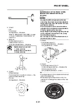
2. Check:
• Tire
• Front wheel
Damage/wear
→
Replace.
Refer to “CHECKING THE TIRES” on page
3-13 and “CHECKING THE WHEELS” on
page 3-13.
3. Measure:
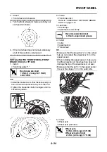
• Radial wheel runout “1”
• Lateral wheel runout “2”
Over the specified limits
→
Replace.
4. Check:
• Wheel bearings
Front wheel turns roughly or is loose
→
Re-
place the wheel bearings.
• Oil seal
Damage/wear
→
Replace.
EAS2DM1003
MAINTENANCE OF THE FRONT WHEEL
SENSOR AND SENSOR ROTOR (for
YP125RA)
NOTICE
ECA2DM1004
• Handle the ABS components with care
since they have been accurately adjusted.
Keep them away from dirt and do not sub-
ject them to shocks.
• The front wheel sensor cannot be disas-
sembled. Do not attempt to disassemble it.
If faulty, replace with a new one.
• Keep magnets (including magnetic pick-up
tools, magnetic screwdrivers, etc.) away
from the wheel sensor.
• Do not drop or shock the wheel sensor or
the wheel sensor rotor.
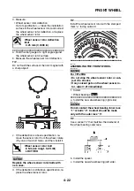
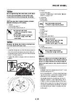
1. Check:
• Front wheel sensor “1”
Cracks/bends/distortion
→
Replace.
Iron powder/dust
→
Clean.
2. Check:
• Front wheel sensor rotor “1”
Cracks/damage/scratches
→
Replace the
front wheel sensor rotor.
Iron powder/dust/solvent
→
Clean.
TIP
• The wheel sensor rotor is installed on the inner
side of the wheel hub.
• When cleaning the wheel sensor rotor, be
careful not to damage the surface of the rotor
magnet.
Radial wheel runout limit
1.0 mm (0.04 in)
Lateral wheel runout limit
0.5 mm (0.02 in)
1
Summary of Contents for MBK XMAX 2014
Page 1: ...2014 SERVICE MANUAL YP125R YP125RA 2DM F8197 E0 ...
Page 6: ......
Page 8: ......
Page 64: ...TIGHTENING TORQUES 2 17 Muffler tightening sequence 1 2 3 ...
Page 72: ...LUBRICATION SYSTEM DIAGRAMS 2 25 EAS2DM1116 LUBRICATION SYSTEM DIAGRAMS 1 2 3 4 5 3 ...
Page 78: ...CABLE ROUTING 2 31 Steering head front view 1 2 3 4 5 6 8 8 A 7 7 ...
Page 80: ...CABLE ROUTING 2 33 Front brake left side view for YP125R 1 2 2 1 1 2 2 D E A B C ...
Page 82: ...CABLE ROUTING 2 35 Front brake left side view for YP125RA 2 1 1 2 1 2 2 A B D E C ...
Page 92: ...CABLE ROUTING 2 45 Frame right side view 3 2 4 1 2 3 A B 6 5 3 A B 3 3 2 3 3 A A B A B B 3 ...
Page 94: ...CABLE ROUTING 2 47 Engine right side view 6 6 6 6 C D C D D C 10 B 9 5 6 1 2 8 3 4 5 6 7 A ...
Page 98: ...CABLE ROUTING 2 51 Frame left side view C D C D 2 1 E 1 2 D C 6 1 4 5 3 2 1 7 3 2 1 A B ...
Page 100: ...CABLE ROUTING 2 53 Engine left side view 1 1 1 1 1 2 3 4 5 6 7 8 9 7 7 A B A B A B 1 ...
Page 106: ...CABLE ROUTING 2 59 Rear brake right side view 2 2 2 2 2 2 1 1 2 3 A B C 3 ...
Page 110: ...CABLE ROUTING 2 63 ...
Page 228: ...REAR SHOCK ABSORBER ASSEMBLIES AND SWINGARM 4 89 ...
Page 231: ......
Page 291: ...CRANKSHAFT 5 60 a 1 ...
Page 292: ...CRANKSHAFT 5 61 ...
Page 302: ...WATER PUMP 6 9 ...
Page 313: ......
Page 331: ...CHARGING SYSTEM 8 18 ...
Page 349: ...COOLING SYSTEM 8 36 ...
Page 391: ...FUEL PUMP SYSTEM 8 78 ...
Page 400: ...IMMOBILIZER SYSTEM 8 87 a Light on b Light off ...
Page 401: ...IMMOBILIZER SYSTEM 8 88 ...
Page 405: ...ABS ANTI LOCK BRAKE SYSTEM for YP125RA 8 92 ...
Page 439: ...ABS ANTI LOCK BRAKE SYSTEM for YP125RA 8 126 ...
Page 464: ...ELECTRICAL COMPONENTS 8 151 ...
Page 476: ......
Page 477: ......
Page 478: ......


