REAR WHEEL
4-29
EAS2DM1006
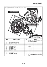
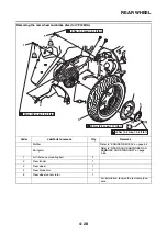
REMOVING THE REAR WHEEL (DISC) (for
YP125R)
1. Stand the vehicle on a level surface.
WARNING
EWA13120
Securely support the vehicle so that there is
no danger of it falling over.
TIP
Place the vehicle on the centerstand so that the
rear wheel is elevated. Also, place a suitable
stand under the engine.
EAS2DM1007
REMOVING THE REAR WHEEL (DISC) (for
YP125RA)
NOTICE
ECA2DM1008
Keep any type of magnets (including mag-
netic pick-up tools, magnetic screwdrivers,
etc.) away from the rear wheel sensor rotor;
otherwise, the rotor may be damaged, result-
ing in improper performance of the ABS sys-
tem.
1. Stand the vehicle on a level surface.
WARNING
EWA13120
Securely support the vehicle so that there is
no danger of it falling over.
TIP
Place the vehicle on a suitable stand so that the
rear wheel is elevated.
EAS22090
CHECKING THE REAR WHEEL
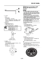
1. Check:
• Tire
• Rear wheel
Damage/wear
→
Replace.
Refer to “CHECKING THE TIRES” on page
3-13 and “CHECKING THE WHEELS” on
page 3-13.
2. Measure:
• Radial wheel runout
• Lateral wheel runout
Refer to “CHECKING THE FRONT WHEEL”
on page 4-20.
EAS2DM1008
MAINTENANCE OF THE REAR WHEEL
SENSOR ROTOR (for YP125RA)
NOTICE
ECA2DM1009
• Handle the ABS components with care
since they have been accurately adjusted.
Keep them away from dirt and do not sub-
ject them to shocks.
• Keep magnets (including magnetic pick-up
tools, magnetic screwdrivers, etc.) away
from the wheel sensor rotor.
• Do not drop or shock the wheel sensor ro-
tor.
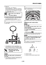
1. Check:
• Rear wheel sensor rotor
Refer to “MAINTENANCE OF THE FRONT
WHEEL SENSOR AND SENSOR ROTOR
(for YP125RA)” on page 4-21.
2. Measure:
• Wheel sensor rotor deflection
Refer to “MAINTENANCE OF THE FRONT
WHEEL SENSOR AND SENSOR ROTOR
(for YP125RA)” on page 4-21.
EAS22150
ADJUSTING THE REAR WHEEL STATIC
BALANCE
TIP
• After replacing the tire, wheel or both, the rear
wheel static balance should be adjusted.
• Adjust the rear wheel static balance with the
brake disc installed.
1. Adjust:
• Rear wheel static balance
Refer to “ADJUSTING THE FRONT WHEEL
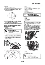
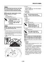
STATIC BALANCE” on page 4-23.
EAS28770
INSTALLING THE REAR WHEEL (REAR
BRAKE DISC)
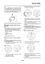
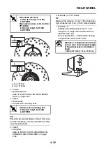
1. Install:
• Rear brake disc “1”
• Rear wheel sensor rotor “2” (for YP125RA)
TIP
• Install the brake disc so that the recessed por-
tion of the bolt hole faces away from the hub.
• Install the wheel sensor rotor with the stamped
mark “a” facing outward. (For YP125RA)
• Tighten the bolts in stages and in a crisscross
pattern.
Radial wheel runout limit
1.0 mm (0.04 in)
Lateral wheel runout limit
0.5 mm (0.02 in)
Summary of Contents for MBK XMAX 2014
Page 1: ...2014 SERVICE MANUAL YP125R YP125RA 2DM F8197 E0 ...
Page 6: ......
Page 8: ......
Page 64: ...TIGHTENING TORQUES 2 17 Muffler tightening sequence 1 2 3 ...
Page 72: ...LUBRICATION SYSTEM DIAGRAMS 2 25 EAS2DM1116 LUBRICATION SYSTEM DIAGRAMS 1 2 3 4 5 3 ...
Page 78: ...CABLE ROUTING 2 31 Steering head front view 1 2 3 4 5 6 8 8 A 7 7 ...
Page 80: ...CABLE ROUTING 2 33 Front brake left side view for YP125R 1 2 2 1 1 2 2 D E A B C ...
Page 82: ...CABLE ROUTING 2 35 Front brake left side view for YP125RA 2 1 1 2 1 2 2 A B D E C ...
Page 92: ...CABLE ROUTING 2 45 Frame right side view 3 2 4 1 2 3 A B 6 5 3 A B 3 3 2 3 3 A A B A B B 3 ...
Page 94: ...CABLE ROUTING 2 47 Engine right side view 6 6 6 6 C D C D D C 10 B 9 5 6 1 2 8 3 4 5 6 7 A ...
Page 98: ...CABLE ROUTING 2 51 Frame left side view C D C D 2 1 E 1 2 D C 6 1 4 5 3 2 1 7 3 2 1 A B ...
Page 100: ...CABLE ROUTING 2 53 Engine left side view 1 1 1 1 1 2 3 4 5 6 7 8 9 7 7 A B A B A B 1 ...
Page 106: ...CABLE ROUTING 2 59 Rear brake right side view 2 2 2 2 2 2 1 1 2 3 A B C 3 ...
Page 110: ...CABLE ROUTING 2 63 ...
Page 228: ...REAR SHOCK ABSORBER ASSEMBLIES AND SWINGARM 4 89 ...
Page 231: ......
Page 291: ...CRANKSHAFT 5 60 a 1 ...
Page 292: ...CRANKSHAFT 5 61 ...
Page 302: ...WATER PUMP 6 9 ...
Page 313: ......
Page 331: ...CHARGING SYSTEM 8 18 ...
Page 349: ...COOLING SYSTEM 8 36 ...
Page 391: ...FUEL PUMP SYSTEM 8 78 ...
Page 400: ...IMMOBILIZER SYSTEM 8 87 a Light on b Light off ...
Page 401: ...IMMOBILIZER SYSTEM 8 88 ...
Page 405: ...ABS ANTI LOCK BRAKE SYSTEM for YP125RA 8 92 ...
Page 439: ...ABS ANTI LOCK BRAKE SYSTEM for YP125RA 8 126 ...
Page 464: ...ELECTRICAL COMPONENTS 8 151 ...
Page 476: ......
Page 477: ......
Page 478: ......


