ABS (ANTI-LOCK BRAKE SYSTEM) (for YP125RA)
4-67
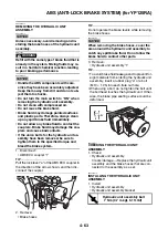
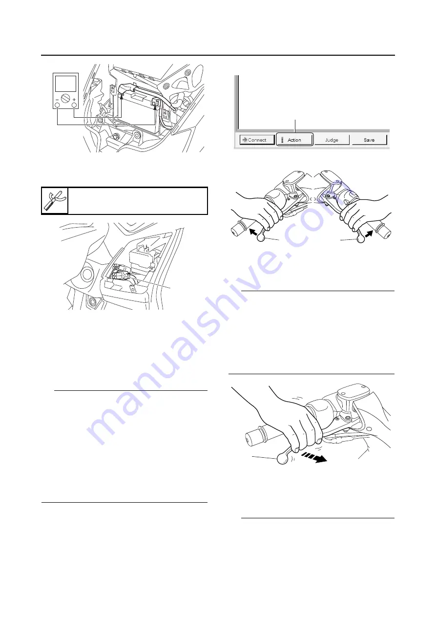
5. Removing the protective cap “1”, and then
connect the Yamaha diagnostic tool to the
ABS test coupler (4P).
6. Start the Yamaha diagnostic tool and display
the diagnosis mode screen.
7. Select code No. 1, “ABS reaction-force con-
firmation”.
8. Click “Action” “1”, and then operate the front
brake lever “2” and rear brake lever “3” simul-
taneously.
TIP
• The hydraulic unit operates 1 second after the
front brake lever and rear brake lever are oper-
ated simultaneously and continues for approx-
imately 5 seconds.
• The operation of the hydraulic unit can be con-
firmed using the indicator.
On: The hydraulic unit is operating.
Flashing: The conditions for operating the hy-
draulic unit have not been met.
Off: The front brake lever and rear brake lever
are not being operated.
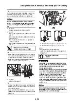
9. A reaction-force pulsating action is generated
in the front brake lever “1” and continues for a
few seconds.
TIP
• The reaction-force pulsating action consists of
quick pulses.
• Be sure to continue operating the front brake
lever and rear brake lever even after the pul-
sating action has stopped.
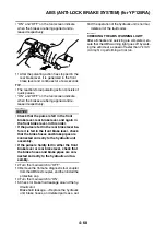
• “ON” and “OFF” on the tool screen indicate
when the brakes are being applied and re-
leased respectively.
10.After the pulsating action has stopped in the
front brake lever, it is generated in the rear
brake lever “1” and continues for a few sec-
onds.
TIP
• The reaction-force pulsating action consists of
quick pulses.
• Be sure to continue operating the front brake
lever and rear brake lever even after the pul-
sating action has stopped.
Yamaha diagnostic tool
90890-03215
1
1
3
2
1
Summary of Contents for MBK XMAX 2014
Page 1: ...2014 SERVICE MANUAL YP125R YP125RA 2DM F8197 E0 ...
Page 6: ......
Page 8: ......
Page 64: ...TIGHTENING TORQUES 2 17 Muffler tightening sequence 1 2 3 ...
Page 72: ...LUBRICATION SYSTEM DIAGRAMS 2 25 EAS2DM1116 LUBRICATION SYSTEM DIAGRAMS 1 2 3 4 5 3 ...
Page 78: ...CABLE ROUTING 2 31 Steering head front view 1 2 3 4 5 6 8 8 A 7 7 ...
Page 80: ...CABLE ROUTING 2 33 Front brake left side view for YP125R 1 2 2 1 1 2 2 D E A B C ...
Page 82: ...CABLE ROUTING 2 35 Front brake left side view for YP125RA 2 1 1 2 1 2 2 A B D E C ...
Page 92: ...CABLE ROUTING 2 45 Frame right side view 3 2 4 1 2 3 A B 6 5 3 A B 3 3 2 3 3 A A B A B B 3 ...
Page 94: ...CABLE ROUTING 2 47 Engine right side view 6 6 6 6 C D C D D C 10 B 9 5 6 1 2 8 3 4 5 6 7 A ...
Page 98: ...CABLE ROUTING 2 51 Frame left side view C D C D 2 1 E 1 2 D C 6 1 4 5 3 2 1 7 3 2 1 A B ...
Page 100: ...CABLE ROUTING 2 53 Engine left side view 1 1 1 1 1 2 3 4 5 6 7 8 9 7 7 A B A B A B 1 ...
Page 106: ...CABLE ROUTING 2 59 Rear brake right side view 2 2 2 2 2 2 1 1 2 3 A B C 3 ...
Page 110: ...CABLE ROUTING 2 63 ...
Page 228: ...REAR SHOCK ABSORBER ASSEMBLIES AND SWINGARM 4 89 ...
Page 231: ......
Page 291: ...CRANKSHAFT 5 60 a 1 ...
Page 292: ...CRANKSHAFT 5 61 ...
Page 302: ...WATER PUMP 6 9 ...
Page 313: ......
Page 331: ...CHARGING SYSTEM 8 18 ...
Page 349: ...COOLING SYSTEM 8 36 ...
Page 391: ...FUEL PUMP SYSTEM 8 78 ...
Page 400: ...IMMOBILIZER SYSTEM 8 87 a Light on b Light off ...
Page 401: ...IMMOBILIZER SYSTEM 8 88 ...
Page 405: ...ABS ANTI LOCK BRAKE SYSTEM for YP125RA 8 92 ...
Page 439: ...ABS ANTI LOCK BRAKE SYSTEM for YP125RA 8 126 ...
Page 464: ...ELECTRICAL COMPONENTS 8 151 ...
Page 476: ......
Page 477: ......
Page 478: ......


