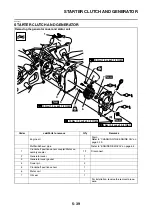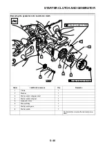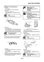
V-BELT AUTOMATIC TRANSMISSION
5-36
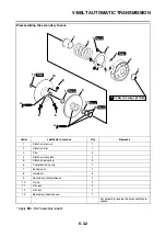
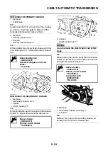
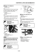
• Primary sliding sheave
• Spacer
• Primary sheave weights
• Cam
2. Lubricate:
• Oil seal
• Primary sliding sheave
• Spacer
TIP
Fill the notches of the primary sliding sheave
with grease. Apply grease to the inner surface of
the primary sliding sheave as shown.
NOTICE
ECA2DM1032
Do not get any grease on the surfaces of the
sheaves. If any grease gets on the sheaves,
be sure to wipe it off with alcohol, etc.
EAS2DM1061
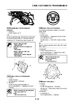
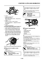
ASSEMBLING THE SECONDARY SHEAVE
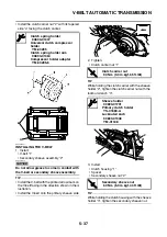
1. Lubricate:
• Secondary fixed sheave inner surface “1”
• Secondary sliding sheave inner surface “2”
• Oil seals
• Bearing
(with the recommended lubricant)
2. Install:
• Oil seal
• Secondary sliding sheave “1”
TIP
Install the secondary sliding sheave onto the
secondary fixed sheave “2” with the oil seal
guide “3”.
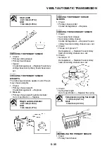
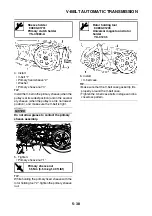
3. Install:
• Guide pins “1”
4. Lubricate:
• Guide pin grooves “2”
• O-rings “3”
(with the recommended lubricant)
5. Install:
• Spring seat
• Compression spring
• Clutch carrier “1”
• Clutch carrier nut “2”
TIP
• While compressing the compression spring
with the clutch spring holder “3” and clutch
spring holder arm “4”, install the clutch carrier
nut.
Recommended lubricant
BEL-RAY assembly lube®
Recommended lubricant
BEL-RAY assembly lube®
Oil seal guide (ø41)
90890-01396
Recommended lubricant
BEL-RAY assembly lube®
New
2
1
3
New
Summary of Contents for MBK XMAX 2014
Page 1: ...2014 SERVICE MANUAL YP125R YP125RA 2DM F8197 E0 ...
Page 6: ......
Page 8: ......
Page 64: ...TIGHTENING TORQUES 2 17 Muffler tightening sequence 1 2 3 ...
Page 72: ...LUBRICATION SYSTEM DIAGRAMS 2 25 EAS2DM1116 LUBRICATION SYSTEM DIAGRAMS 1 2 3 4 5 3 ...
Page 78: ...CABLE ROUTING 2 31 Steering head front view 1 2 3 4 5 6 8 8 A 7 7 ...
Page 80: ...CABLE ROUTING 2 33 Front brake left side view for YP125R 1 2 2 1 1 2 2 D E A B C ...
Page 82: ...CABLE ROUTING 2 35 Front brake left side view for YP125RA 2 1 1 2 1 2 2 A B D E C ...
Page 92: ...CABLE ROUTING 2 45 Frame right side view 3 2 4 1 2 3 A B 6 5 3 A B 3 3 2 3 3 A A B A B B 3 ...
Page 94: ...CABLE ROUTING 2 47 Engine right side view 6 6 6 6 C D C D D C 10 B 9 5 6 1 2 8 3 4 5 6 7 A ...
Page 98: ...CABLE ROUTING 2 51 Frame left side view C D C D 2 1 E 1 2 D C 6 1 4 5 3 2 1 7 3 2 1 A B ...
Page 100: ...CABLE ROUTING 2 53 Engine left side view 1 1 1 1 1 2 3 4 5 6 7 8 9 7 7 A B A B A B 1 ...
Page 106: ...CABLE ROUTING 2 59 Rear brake right side view 2 2 2 2 2 2 1 1 2 3 A B C 3 ...
Page 110: ...CABLE ROUTING 2 63 ...
Page 228: ...REAR SHOCK ABSORBER ASSEMBLIES AND SWINGARM 4 89 ...
Page 231: ......
Page 291: ...CRANKSHAFT 5 60 a 1 ...
Page 292: ...CRANKSHAFT 5 61 ...
Page 302: ...WATER PUMP 6 9 ...
Page 313: ......
Page 331: ...CHARGING SYSTEM 8 18 ...
Page 349: ...COOLING SYSTEM 8 36 ...
Page 391: ...FUEL PUMP SYSTEM 8 78 ...
Page 400: ...IMMOBILIZER SYSTEM 8 87 a Light on b Light off ...
Page 401: ...IMMOBILIZER SYSTEM 8 88 ...
Page 405: ...ABS ANTI LOCK BRAKE SYSTEM for YP125RA 8 92 ...
Page 439: ...ABS ANTI LOCK BRAKE SYSTEM for YP125RA 8 126 ...
Page 464: ...ELECTRICAL COMPONENTS 8 151 ...
Page 476: ......
Page 477: ......
Page 478: ......


