STARTER CLUTCH AND GENERATOR
5-42
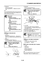
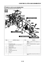
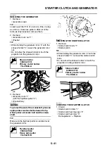
2. Check:
• Starter clutch idle gear
• Starter clutch gear
Burrs/chips/roughness/wear
→
Replace the
defective part(s).
3. Check:
• Starter clutch gear contact surfaces
Damage/pitting/wear
→
Replace the starter
clutch gear.
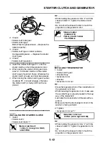
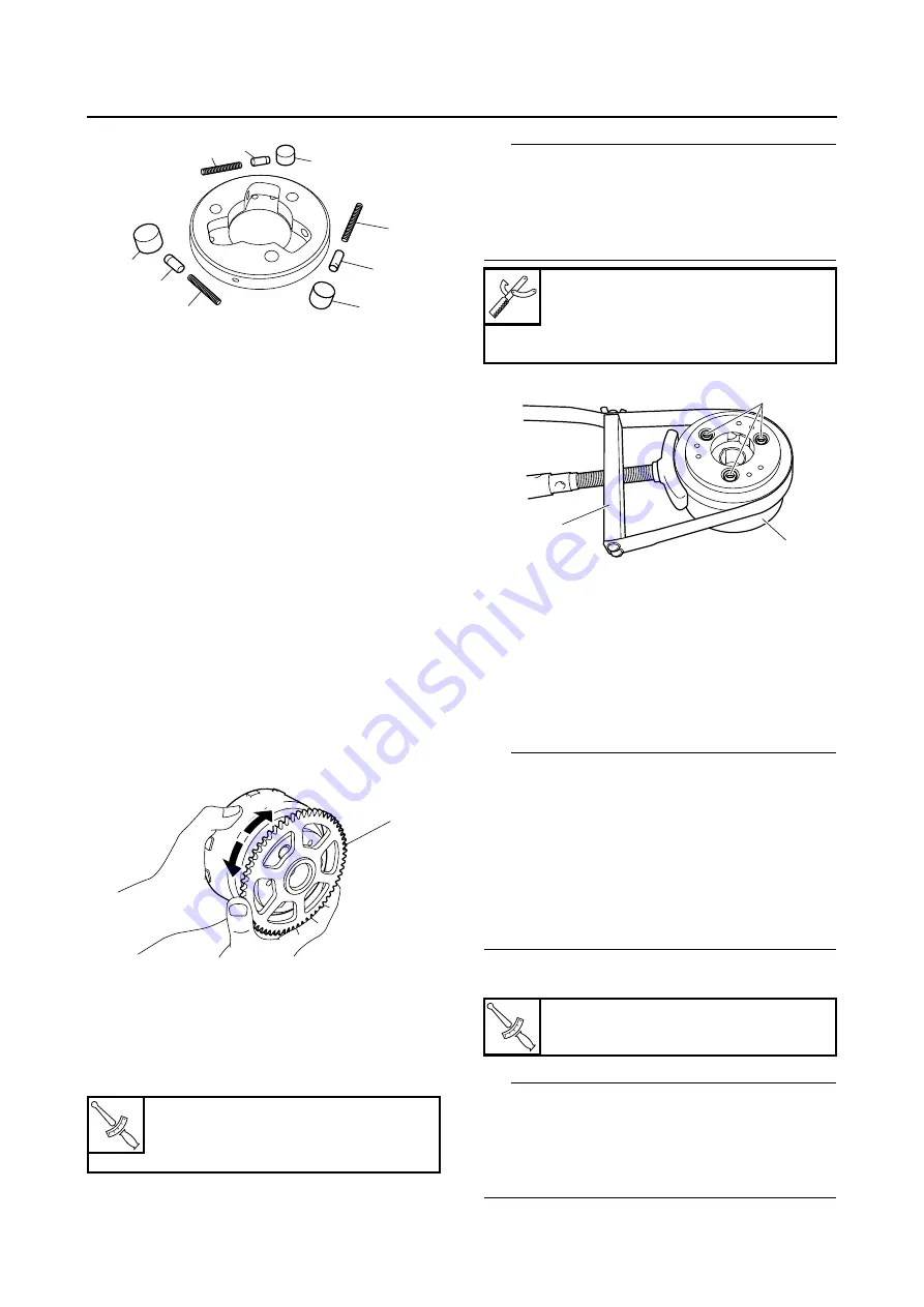
4. Check:
• Starter clutch operation
▼▼▼
▼
▼ ▼▼▼
▼
▼ ▼▼▼
▼
▼ ▼▼▼
▼
▼ ▼▼▼
▼
▼ ▼▼▼
▼
▼▼▼
a. Install the starter clutch gear “1” onto the
starter clutch and hold the generator rotor.
b. When turning the starter clutch gear clock-
wise “A”, the starter clutch and the starter
clutch gear should turn freely, otherwise the
starter clutch is faulty and must be replaced.
c. When turning the starter clutch gear counter-
clockwise “B”, it should engage, otherwise
the starter clutch is faulty and must be re-
placed.
▲▲▲
▲
▲ ▲▲▲
▲
▲ ▲▲▲
▲
▲ ▲▲▲
▲
▲ ▲▲▲
▲
▲ ▲▲▲
▲
▲▲▲
EAS2DM1066
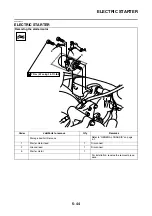
INSTALLING THE STARTER CLUTCH
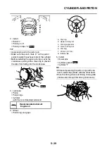
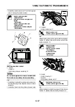
1. Install:
• Starter clutch
• Starter clutch bolts “1”
TIP
• While holding the generator rotor “2” with the
sheave holder “3”, tighten the starter clutch
bolts.
• Do not allow the sheave holder to touch the
projection on the generator rotor.
EAS2DM1067
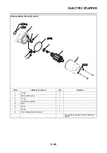
INSTALLING THE GENERATOR
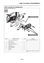
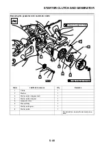
1. Install:
• Starter clutch gear
• Woodruff key
• Generator rotor
• Washer
• Generator rotor nut
TIP
• Clean the tapered portion of the crankshaft and
the generator rotor hub.
• When installing the generator rotor, make sure
the woodruff key is properly seated in the key-
way of the crankshaft.
• Lubricate the crankshaft end threads with en-
gine oil.
• Make sure that the blunt-edged corner of the
washer is facing outward.
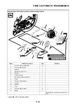
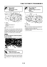
2. Tighten:
• Generator rotor nut “1”
TIP
• While holding the generator rotor “2” with the
sheave holder “3”, tighten the generator rotor
nut.
• Do not allow the sheave holder to touch the
projection on the generator rotor.
T
R
.
.
Starter clutch bolt
13 Nm (1.3 m·kgf, 9.4 ft·lbf)
LOCTITE®
1
1
3
2
3
2
3
2
1
1
A
B
Sheave holder
90890-01701
Primary clutch holder
YS-01880-A
T
R
.
.
Generator rotor nut
80 Nm (8.0 m·kgf, 58 ft·lbf)
1
3
2
Summary of Contents for MBK XMAX 2014
Page 1: ...2014 SERVICE MANUAL YP125R YP125RA 2DM F8197 E0 ...
Page 6: ......
Page 8: ......
Page 64: ...TIGHTENING TORQUES 2 17 Muffler tightening sequence 1 2 3 ...
Page 72: ...LUBRICATION SYSTEM DIAGRAMS 2 25 EAS2DM1116 LUBRICATION SYSTEM DIAGRAMS 1 2 3 4 5 3 ...
Page 78: ...CABLE ROUTING 2 31 Steering head front view 1 2 3 4 5 6 8 8 A 7 7 ...
Page 80: ...CABLE ROUTING 2 33 Front brake left side view for YP125R 1 2 2 1 1 2 2 D E A B C ...
Page 82: ...CABLE ROUTING 2 35 Front brake left side view for YP125RA 2 1 1 2 1 2 2 A B D E C ...
Page 92: ...CABLE ROUTING 2 45 Frame right side view 3 2 4 1 2 3 A B 6 5 3 A B 3 3 2 3 3 A A B A B B 3 ...
Page 94: ...CABLE ROUTING 2 47 Engine right side view 6 6 6 6 C D C D D C 10 B 9 5 6 1 2 8 3 4 5 6 7 A ...
Page 98: ...CABLE ROUTING 2 51 Frame left side view C D C D 2 1 E 1 2 D C 6 1 4 5 3 2 1 7 3 2 1 A B ...
Page 100: ...CABLE ROUTING 2 53 Engine left side view 1 1 1 1 1 2 3 4 5 6 7 8 9 7 7 A B A B A B 1 ...
Page 106: ...CABLE ROUTING 2 59 Rear brake right side view 2 2 2 2 2 2 1 1 2 3 A B C 3 ...
Page 110: ...CABLE ROUTING 2 63 ...
Page 228: ...REAR SHOCK ABSORBER ASSEMBLIES AND SWINGARM 4 89 ...
Page 231: ......
Page 291: ...CRANKSHAFT 5 60 a 1 ...
Page 292: ...CRANKSHAFT 5 61 ...
Page 302: ...WATER PUMP 6 9 ...
Page 313: ......
Page 331: ...CHARGING SYSTEM 8 18 ...
Page 349: ...COOLING SYSTEM 8 36 ...
Page 391: ...FUEL PUMP SYSTEM 8 78 ...
Page 400: ...IMMOBILIZER SYSTEM 8 87 a Light on b Light off ...
Page 401: ...IMMOBILIZER SYSTEM 8 88 ...
Page 405: ...ABS ANTI LOCK BRAKE SYSTEM for YP125RA 8 92 ...
Page 439: ...ABS ANTI LOCK BRAKE SYSTEM for YP125RA 8 126 ...
Page 464: ...ELECTRICAL COMPONENTS 8 151 ...
Page 476: ......
Page 477: ......
Page 478: ......

