FUEL INJECTION SYSTEM
8-64
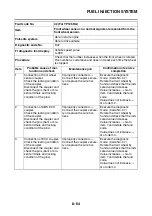
Fault code No.
42 (For YP125RA)
Item
Front wheel sensor: no normal signals are received from the
front wheel sensor.
Fail-safe system
Able to start engine
Able to drive vehicle
Diagnostic code No.
D07
FI diagnostic tool display
Vehicle speed pulse
0–999
Procedure
Check that the number increases when the front wheel is rotated.
The number is cumulative and does not reset each time the wheel
is stopped.
Item
Probable cause of mal-
function and check
Maintenance job
Confirmation of service
completion
1
Connection of front wheel
sensor coupler.
Check the locking condition
of the coupler.
Disconnect the coupler and
check the pins (bent or bro-
ken terminals and locking
condition of the pins).
Improperly connected
→
Connect the coupler secure-
ly or replace the wire har-
ness.
Execute the diagnostic
mode. (Code No. 07)
Rotate the front wheel by
hand and check that the indi-
cated value increases.
Value increases
→
Go to
item 7 and delete the fault
code.
Value does not increase
→
Go to item 2.
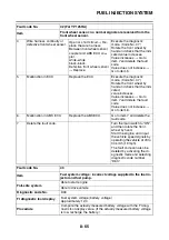
2
Connection of ABS ECU
coupler.
Check the locking condition
of the coupler.
Disconnect the coupler and
check the pins (bent or bro-
ken terminals and locking
condition of the pins).
Improperly connected
→
Connect the coupler secure-
ly or replace the wire har-
ness.
Execute the diagnostic
mode. (Code No. 07)
Rotate the front wheel by
hand and check that the indi-
cated value increases.
Value increases
→
Go to
item 7 and delete the fault
code.
Value does not increase
→
Go to item 3.
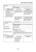
3
Connection of ECU coupler.
Check the locking condition
of the coupler.
Disconnect the coupler and
check the pins (bent or bro-
ken terminals and locking
condition of the pins).
Improperly connected
→
Connect the coupler secure-
ly or replace the wire har-
ness.
Execute the diagnostic
mode. (Code No. 07)
Rotate the front wheel by
hand and check that the indi-
cated value increases.
Value increases
→
Go to
item 7 and delete the fault
code.
Value does not increase
→
Go to item 4.
Summary of Contents for MBK XMAX 2014
Page 1: ...2014 SERVICE MANUAL YP125R YP125RA 2DM F8197 E0 ...
Page 6: ......
Page 8: ......
Page 64: ...TIGHTENING TORQUES 2 17 Muffler tightening sequence 1 2 3 ...
Page 72: ...LUBRICATION SYSTEM DIAGRAMS 2 25 EAS2DM1116 LUBRICATION SYSTEM DIAGRAMS 1 2 3 4 5 3 ...
Page 78: ...CABLE ROUTING 2 31 Steering head front view 1 2 3 4 5 6 8 8 A 7 7 ...
Page 80: ...CABLE ROUTING 2 33 Front brake left side view for YP125R 1 2 2 1 1 2 2 D E A B C ...
Page 82: ...CABLE ROUTING 2 35 Front brake left side view for YP125RA 2 1 1 2 1 2 2 A B D E C ...
Page 92: ...CABLE ROUTING 2 45 Frame right side view 3 2 4 1 2 3 A B 6 5 3 A B 3 3 2 3 3 A A B A B B 3 ...
Page 94: ...CABLE ROUTING 2 47 Engine right side view 6 6 6 6 C D C D D C 10 B 9 5 6 1 2 8 3 4 5 6 7 A ...
Page 98: ...CABLE ROUTING 2 51 Frame left side view C D C D 2 1 E 1 2 D C 6 1 4 5 3 2 1 7 3 2 1 A B ...
Page 100: ...CABLE ROUTING 2 53 Engine left side view 1 1 1 1 1 2 3 4 5 6 7 8 9 7 7 A B A B A B 1 ...
Page 106: ...CABLE ROUTING 2 59 Rear brake right side view 2 2 2 2 2 2 1 1 2 3 A B C 3 ...
Page 110: ...CABLE ROUTING 2 63 ...
Page 228: ...REAR SHOCK ABSORBER ASSEMBLIES AND SWINGARM 4 89 ...
Page 231: ......
Page 291: ...CRANKSHAFT 5 60 a 1 ...
Page 292: ...CRANKSHAFT 5 61 ...
Page 302: ...WATER PUMP 6 9 ...
Page 313: ......
Page 331: ...CHARGING SYSTEM 8 18 ...
Page 349: ...COOLING SYSTEM 8 36 ...
Page 391: ...FUEL PUMP SYSTEM 8 78 ...
Page 400: ...IMMOBILIZER SYSTEM 8 87 a Light on b Light off ...
Page 401: ...IMMOBILIZER SYSTEM 8 88 ...
Page 405: ...ABS ANTI LOCK BRAKE SYSTEM for YP125RA 8 92 ...
Page 439: ...ABS ANTI LOCK BRAKE SYSTEM for YP125RA 8 126 ...
Page 464: ...ELECTRICAL COMPONENTS 8 151 ...
Page 476: ......
Page 477: ......
Page 478: ......

