ELECTRICAL COMPONENTS
8-147
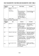
c. Check the radiator fan motor movement.
▲▲▲
▲
▲ ▲▲▲
▲
▲ ▲▲▲
▲
▲ ▲▲▲
▲
▲ ▲▲▲
▲
▲ ▲▲▲
▲
▲▲▲
EAS28260
CHECKING THE COOLANT TEMPERATURE
SENSOR
1. Remove:
• Coolant temperature sensor
Refer to “CYLINDER HEAD” on page 5-7.
WARNING
EWA14130
• Handle the coolant temperature sensor
with special care.
• Never subject the coolant temperature sen-
sor to strong shocks. If the coolant temper-
ature sensor is dropped, replace it.
2. Check:
• Coolant temperature sensor resistance
Out of specification
→
Replace.
▼▼▼
▼
▼ ▼▼▼
▼
▼ ▼▼▼
▼
▼ ▼▼▼
▼
▼ ▼▼▼
▼
▼ ▼▼▼
▼
▼▼▼
a. Connect the pocket tester (
Ω
×
1k
×
100) to
the coolant temperature sensor terminals as
shown.
b. Immerse the coolant temperature sensor “1”
in a container filled with coolant “2”.
TIP
Make sure the coolant temperature sensor ter-
minals do not get wet.
c. Place a thermometer “3” in the coolant.
d. Heat the coolant or let it cool down to the
specified temperatures.
e. Measure the coolant temperature sensor re-
sistances.
▲▲▲
▲
▲ ▲▲▲
▲
▲ ▲▲▲
▲
▲ ▲▲▲
▲
▲ ▲▲▲
▲
▲ ▲▲▲
▲
▲▲▲
3. Install:
• Coolant temperature sensor
EAS28300
CHECKING THE THROTTLE POSITION
SENSOR
1. Check:
• Throttle position sensor
▼▼▼
▼
▼ ▼▼▼
▼
▼ ▼▼▼
▼
▼ ▼▼▼
▼
▼ ▼▼▼
▼
▼ ▼▼▼
▼
▼▼▼
a. Connect the test harness- TPS 5RU (3P) “1”
to the throttle position sensor and wire har-
ness as shown.
b. Connect the digital circuit tester (DCV) to the
test harness- TPS 5RU (3P).
c. Measure the throttle position sensor voltage.
Out of specification
→
Replace the wire har-
ness.
d. Connect the digital circuit tester to the test
harness- TPS 5RU (3P).
Coolant temperature sensor re-
sistance
2.32–2.59 k
Ω
at 20 °C (68 °F)
310–326
Ω
at 80 °C (176 °F)
Pocket tester
90890-03112
Analog pocket tester
YU-03112-C
3
1
2
T
R
.
.
Coolant temperature sensor
18 Nm (1.8 m·kgf, 13 ft·lbf)
Test harness– TPS 5RU (3P)
90890-03230
Digital circuit tester
90890-03174
Model 88 Multimeter with ta-
chometer
YU-A1927
• Positive tester probe
→
blue (wire harness color)
• Negative tester probe
→
black/blue (wire harness color)
Throttle position sensor voltage
5 V
(blue–black/blue)
1
Summary of Contents for MBK XMAX 2014
Page 1: ...2014 SERVICE MANUAL YP125R YP125RA 2DM F8197 E0 ...
Page 6: ......
Page 8: ......
Page 64: ...TIGHTENING TORQUES 2 17 Muffler tightening sequence 1 2 3 ...
Page 72: ...LUBRICATION SYSTEM DIAGRAMS 2 25 EAS2DM1116 LUBRICATION SYSTEM DIAGRAMS 1 2 3 4 5 3 ...
Page 78: ...CABLE ROUTING 2 31 Steering head front view 1 2 3 4 5 6 8 8 A 7 7 ...
Page 80: ...CABLE ROUTING 2 33 Front brake left side view for YP125R 1 2 2 1 1 2 2 D E A B C ...
Page 82: ...CABLE ROUTING 2 35 Front brake left side view for YP125RA 2 1 1 2 1 2 2 A B D E C ...
Page 92: ...CABLE ROUTING 2 45 Frame right side view 3 2 4 1 2 3 A B 6 5 3 A B 3 3 2 3 3 A A B A B B 3 ...
Page 94: ...CABLE ROUTING 2 47 Engine right side view 6 6 6 6 C D C D D C 10 B 9 5 6 1 2 8 3 4 5 6 7 A ...
Page 98: ...CABLE ROUTING 2 51 Frame left side view C D C D 2 1 E 1 2 D C 6 1 4 5 3 2 1 7 3 2 1 A B ...
Page 100: ...CABLE ROUTING 2 53 Engine left side view 1 1 1 1 1 2 3 4 5 6 7 8 9 7 7 A B A B A B 1 ...
Page 106: ...CABLE ROUTING 2 59 Rear brake right side view 2 2 2 2 2 2 1 1 2 3 A B C 3 ...
Page 110: ...CABLE ROUTING 2 63 ...
Page 228: ...REAR SHOCK ABSORBER ASSEMBLIES AND SWINGARM 4 89 ...
Page 231: ......
Page 291: ...CRANKSHAFT 5 60 a 1 ...
Page 292: ...CRANKSHAFT 5 61 ...
Page 302: ...WATER PUMP 6 9 ...
Page 313: ......
Page 331: ...CHARGING SYSTEM 8 18 ...
Page 349: ...COOLING SYSTEM 8 36 ...
Page 391: ...FUEL PUMP SYSTEM 8 78 ...
Page 400: ...IMMOBILIZER SYSTEM 8 87 a Light on b Light off ...
Page 401: ...IMMOBILIZER SYSTEM 8 88 ...
Page 405: ...ABS ANTI LOCK BRAKE SYSTEM for YP125RA 8 92 ...
Page 439: ...ABS ANTI LOCK BRAKE SYSTEM for YP125RA 8 126 ...
Page 464: ...ELECTRICAL COMPONENTS 8 151 ...
Page 476: ......
Page 477: ......
Page 478: ......


