PERIODIC MAINTENANCE
3-15
WARNING
EWA2DM1017
After extensive tests, the tires listed below
have been approved by MBK industrie for
this model. The front and rear tires should al-
ways be by the same manufacturer and of
the same design. No guarantee concerning
handling characteristics can be given if a tire
combination other than one approved by
MBK industrie is used on this vehicle.
WARNING
EWA2DM1006
New tires have a relatively low grip on the
road surface until they have been slightly
worn. Therefore, approximately 100 km
should be traveled at normal speed before
any high-speed riding is done.
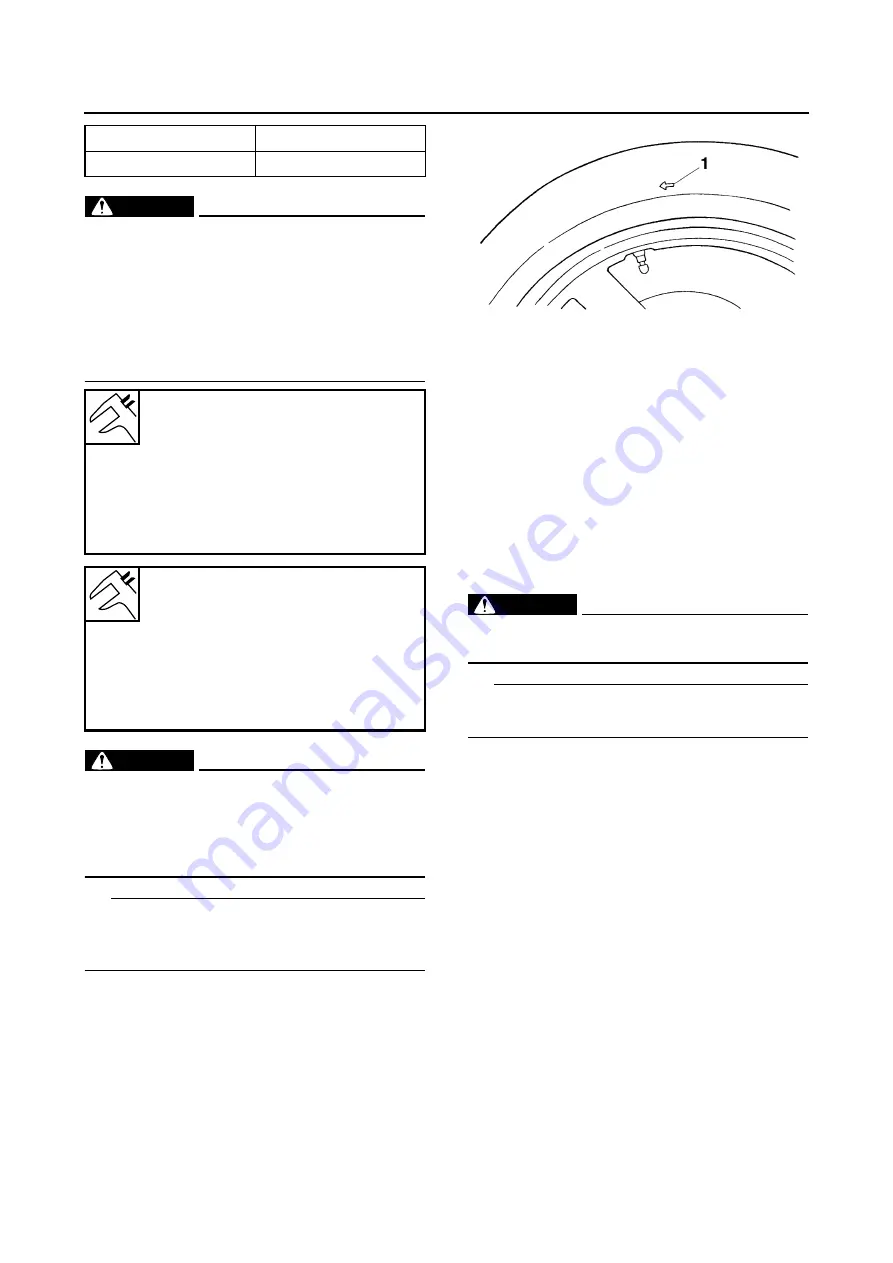
TIP
For tires with a direction of rotation mark “1”:
Install the tire with the mark pointing in the direc-
tion of wheel rotation.
EAS1SD1004
CHECKING THE WHEEL BEARINGS
The following procedure applies to all of the
wheel bearings.
1. Check:
• Wheel bearings
Refer to “CHECKING THE FRONT WHEEL”
on page 4-20 and “CHECKING THE REAR
WHEEL” on page 4-29.
EAS21520
CHECKING AND ADJUSTING THE
STEERING HEAD
1. Stand the vehicle on a level surface.
WARNING
EWA13120
Securely support the vehicle so that there is
no danger of it falling over.
TIP
Place the vehicle on a suitable stand so that the
front wheel is elevated.
2. Check:
• Steering head
Grasp the bottom of the front fork legs and
gently rock the front fork.
Binding/looseness
→
Adjust the steering
head.
3. Remove:
• Lower handlebar holder
Refer to “STEERING HEAD” on page 4-81.
4. Adjust:
• Steering head
▼▼▼
▼
▼ ▼▼▼
▼
▼ ▼▼▼
▼
▼ ▼▼▼
▼
▼ ▼▼▼
▼
▼ ▼▼▼
▼
▼▼▼
a. Remove the upper ring nut “1”, the lock wash-
er “2”, the center ring nut “3” and the rubber
washer.
Tube wheel
Tube tire only
Tubeless wheel
Tube or tubeless tire
Front tire
Size
120/70–15 M/C 56P(METZELER)-
56S(MICHELIN)
Manufacturer/model
METZELER / FEELFREE
Manufacturer/model
MICHELIN / CITYGRIP
Rear tire
Size
140/70–14 M/C 68P(METZELER)-
68S(MICHELIN)
Manufacturer/model
METZELER / FEELFREE
Manufacturer/model
MICHELIN / CITYGRIP
Summary of Contents for MBK XMAX 2014
Page 1: ...2014 SERVICE MANUAL YP125R YP125RA 2DM F8197 E0 ...
Page 6: ......
Page 8: ......
Page 64: ...TIGHTENING TORQUES 2 17 Muffler tightening sequence 1 2 3 ...
Page 72: ...LUBRICATION SYSTEM DIAGRAMS 2 25 EAS2DM1116 LUBRICATION SYSTEM DIAGRAMS 1 2 3 4 5 3 ...
Page 78: ...CABLE ROUTING 2 31 Steering head front view 1 2 3 4 5 6 8 8 A 7 7 ...
Page 80: ...CABLE ROUTING 2 33 Front brake left side view for YP125R 1 2 2 1 1 2 2 D E A B C ...
Page 82: ...CABLE ROUTING 2 35 Front brake left side view for YP125RA 2 1 1 2 1 2 2 A B D E C ...
Page 92: ...CABLE ROUTING 2 45 Frame right side view 3 2 4 1 2 3 A B 6 5 3 A B 3 3 2 3 3 A A B A B B 3 ...
Page 94: ...CABLE ROUTING 2 47 Engine right side view 6 6 6 6 C D C D D C 10 B 9 5 6 1 2 8 3 4 5 6 7 A ...
Page 98: ...CABLE ROUTING 2 51 Frame left side view C D C D 2 1 E 1 2 D C 6 1 4 5 3 2 1 7 3 2 1 A B ...
Page 100: ...CABLE ROUTING 2 53 Engine left side view 1 1 1 1 1 2 3 4 5 6 7 8 9 7 7 A B A B A B 1 ...
Page 106: ...CABLE ROUTING 2 59 Rear brake right side view 2 2 2 2 2 2 1 1 2 3 A B C 3 ...
Page 110: ...CABLE ROUTING 2 63 ...
Page 228: ...REAR SHOCK ABSORBER ASSEMBLIES AND SWINGARM 4 89 ...
Page 231: ......
Page 291: ...CRANKSHAFT 5 60 a 1 ...
Page 292: ...CRANKSHAFT 5 61 ...
Page 302: ...WATER PUMP 6 9 ...
Page 313: ......
Page 331: ...CHARGING SYSTEM 8 18 ...
Page 349: ...COOLING SYSTEM 8 36 ...
Page 391: ...FUEL PUMP SYSTEM 8 78 ...
Page 400: ...IMMOBILIZER SYSTEM 8 87 a Light on b Light off ...
Page 401: ...IMMOBILIZER SYSTEM 8 88 ...
Page 405: ...ABS ANTI LOCK BRAKE SYSTEM for YP125RA 8 92 ...
Page 439: ...ABS ANTI LOCK BRAKE SYSTEM for YP125RA 8 126 ...
Page 464: ...ELECTRICAL COMPONENTS 8 151 ...
Page 476: ......
Page 477: ......
Page 478: ......


