PERIODIC MAINTENANCE
3-18
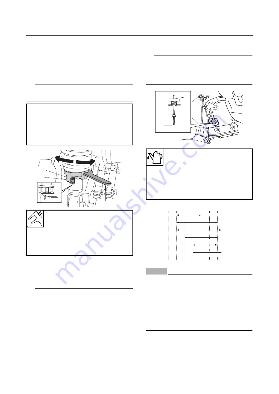
1. Adjust:
• Spring preload
▼▼▼
▼
▼ ▼▼▼
▼
▼ ▼▼▼
▼
▼ ▼▼▼
▼
▼ ▼▼▼
▼
▼ ▼▼▼
▼
▼▼▼
a. Turn the spring preload adjusting ring “1” in
direction “a” or “b”.
b. Align the desired position on the spring seat
with the stopper “2”.
TIP
Adjust the spring preload with the special
wrench “3” included in the owner’s tool kit.
▲▲▲
▲
▲ ▲▲▲
▲
▲ ▲▲▲
▲
▲ ▲▲▲
▲
▲ ▲▲▲
▲
▲ ▲▲▲
▲
▲▲▲
EAS2DM1028
CHECKING THE ENGINE OIL LEVEL
1. Stand the vehicle on a level surface.
TIP
• Place the vehicle on the centerstand.
• Make sure the vehicle is upright.
2. Start the engine, warm it up for several min-
utes, and then turn it off.
3. Remove:
• Dipstick “1”
4. Check:
• Engine oil level
The engine oil level should be between the
minimum level mark “a” and maximum level
mark “b”.
Below the minimum level mark
→
Add the
recommended engine oil to the proper level.
TIP
• Before checking the engine oil level, wait a few
minutes until the oil has settled.
• Do not screw the dipstick in when inspecting
the oil level.
NOTICE
ECA2DM1028
Do not allow foreign materials to enter the
crankcase.
5. Start the engine, warm it up for several min-
utes, and then turn it off.
6. Check the engine oil level again.
TIP
Before checking the engine oil level, wait a few
minutes until the oil has settled.
7. Install:
• Dipstick
Direction “a”
Spring preload is increased (suspen-
sion is harder).
Direction “b”
Spring preload is decreased (suspen-
sion is softer).
Spring preload adjusting positions
Minimum
1
Standard
2
Maximum
5
a
b
1
2
3
1
2
3
4
5
Recommended brand
YAMALUBE
Type
SAE 10W-30, 10W-40, 15W-40,
20W-40 or 20W-50
Recommended engine oil grade
API service SG type or higher,
JASO standard MA
a
b
1
-20 -10 0 10 20 30 40 50 ˚C
SAE 10W-30
SAE 15W-40
SAE 20W-40
SAE 20W-50
SAE 10W-40
SAE 10W-50
Summary of Contents for MBK XMAX 2014
Page 1: ...2014 SERVICE MANUAL YP125R YP125RA 2DM F8197 E0 ...
Page 6: ......
Page 8: ......
Page 64: ...TIGHTENING TORQUES 2 17 Muffler tightening sequence 1 2 3 ...
Page 72: ...LUBRICATION SYSTEM DIAGRAMS 2 25 EAS2DM1116 LUBRICATION SYSTEM DIAGRAMS 1 2 3 4 5 3 ...
Page 78: ...CABLE ROUTING 2 31 Steering head front view 1 2 3 4 5 6 8 8 A 7 7 ...
Page 80: ...CABLE ROUTING 2 33 Front brake left side view for YP125R 1 2 2 1 1 2 2 D E A B C ...
Page 82: ...CABLE ROUTING 2 35 Front brake left side view for YP125RA 2 1 1 2 1 2 2 A B D E C ...
Page 92: ...CABLE ROUTING 2 45 Frame right side view 3 2 4 1 2 3 A B 6 5 3 A B 3 3 2 3 3 A A B A B B 3 ...
Page 94: ...CABLE ROUTING 2 47 Engine right side view 6 6 6 6 C D C D D C 10 B 9 5 6 1 2 8 3 4 5 6 7 A ...
Page 98: ...CABLE ROUTING 2 51 Frame left side view C D C D 2 1 E 1 2 D C 6 1 4 5 3 2 1 7 3 2 1 A B ...
Page 100: ...CABLE ROUTING 2 53 Engine left side view 1 1 1 1 1 2 3 4 5 6 7 8 9 7 7 A B A B A B 1 ...
Page 106: ...CABLE ROUTING 2 59 Rear brake right side view 2 2 2 2 2 2 1 1 2 3 A B C 3 ...
Page 110: ...CABLE ROUTING 2 63 ...
Page 228: ...REAR SHOCK ABSORBER ASSEMBLIES AND SWINGARM 4 89 ...
Page 231: ......
Page 291: ...CRANKSHAFT 5 60 a 1 ...
Page 292: ...CRANKSHAFT 5 61 ...
Page 302: ...WATER PUMP 6 9 ...
Page 313: ......
Page 331: ...CHARGING SYSTEM 8 18 ...
Page 349: ...COOLING SYSTEM 8 36 ...
Page 391: ...FUEL PUMP SYSTEM 8 78 ...
Page 400: ...IMMOBILIZER SYSTEM 8 87 a Light on b Light off ...
Page 401: ...IMMOBILIZER SYSTEM 8 88 ...
Page 405: ...ABS ANTI LOCK BRAKE SYSTEM for YP125RA 8 92 ...
Page 439: ...ABS ANTI LOCK BRAKE SYSTEM for YP125RA 8 126 ...
Page 464: ...ELECTRICAL COMPONENTS 8 151 ...
Page 476: ......
Page 477: ......
Page 478: ......


