SIGNALING SYSTEM
8-27
EAS27290
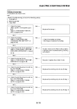
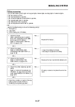
TROUBLESHOOTING
• Any of the following fail to light: turn signal lights, brake lights, warning light or indicator lights.
• The horn fails to sound.
• The fuel meter fails to operate.
• The coolant temperature meter fails to operate.
• The speedometer fails to operate.
• The tachometer fails to operate.
• The air temperature meter fails to operate.
TIP
• Before troubleshooting, remove the following part(s):
1. Storage box
2. Leg shield
3. Front cowling (for YP125RA)
NG
→
OK
↓
NG
→
OK
↓
NG
→
OK
↓
NG
→
OK
↓
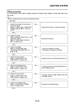
1. Check the fuses.
(Main, signaling system, ignition,
ECU, turn signal/hazard and ABS
ECU fuse (for YP125RA))
Refer to “CHECKING THE FUS-
ES” on page 8-135.
Replace the fuse(s).
2. Check the battery.
Refer to “CHECKING AND
CHARGING THE BATTERY” on
page 8-136.
• Clean the battery terminals.
• Recharge or replace the battery.
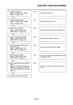
3. Check the main switch.
Refer to “CHECKING THE
SWITCHES” on page 8-131.
Replace the main switch/immobilizer unit.
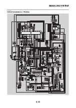
4. Check the entire signaling system
wiring.
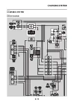
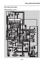
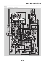
Refer to “CIRCUIT DIAGRAM (for
YP125R)” on page 8-23 and “CIR-
CUIT DIAGRAM (for YP125RA)” on
page 8-25.
Properly connect or replace the wire har-
ness.
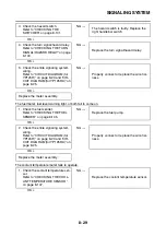
Check the condition of each of the sig-
naling system circuits. Refer to
“Checking the signaling system”.
Summary of Contents for MBK XMAX 2014
Page 1: ...2014 SERVICE MANUAL YP125R YP125RA 2DM F8197 E0 ...
Page 6: ......
Page 8: ......
Page 64: ...TIGHTENING TORQUES 2 17 Muffler tightening sequence 1 2 3 ...
Page 72: ...LUBRICATION SYSTEM DIAGRAMS 2 25 EAS2DM1116 LUBRICATION SYSTEM DIAGRAMS 1 2 3 4 5 3 ...
Page 78: ...CABLE ROUTING 2 31 Steering head front view 1 2 3 4 5 6 8 8 A 7 7 ...
Page 80: ...CABLE ROUTING 2 33 Front brake left side view for YP125R 1 2 2 1 1 2 2 D E A B C ...
Page 82: ...CABLE ROUTING 2 35 Front brake left side view for YP125RA 2 1 1 2 1 2 2 A B D E C ...
Page 92: ...CABLE ROUTING 2 45 Frame right side view 3 2 4 1 2 3 A B 6 5 3 A B 3 3 2 3 3 A A B A B B 3 ...
Page 94: ...CABLE ROUTING 2 47 Engine right side view 6 6 6 6 C D C D D C 10 B 9 5 6 1 2 8 3 4 5 6 7 A ...
Page 98: ...CABLE ROUTING 2 51 Frame left side view C D C D 2 1 E 1 2 D C 6 1 4 5 3 2 1 7 3 2 1 A B ...
Page 100: ...CABLE ROUTING 2 53 Engine left side view 1 1 1 1 1 2 3 4 5 6 7 8 9 7 7 A B A B A B 1 ...
Page 106: ...CABLE ROUTING 2 59 Rear brake right side view 2 2 2 2 2 2 1 1 2 3 A B C 3 ...
Page 110: ...CABLE ROUTING 2 63 ...
Page 228: ...REAR SHOCK ABSORBER ASSEMBLIES AND SWINGARM 4 89 ...
Page 231: ......
Page 291: ...CRANKSHAFT 5 60 a 1 ...
Page 292: ...CRANKSHAFT 5 61 ...
Page 302: ...WATER PUMP 6 9 ...
Page 313: ......
Page 331: ...CHARGING SYSTEM 8 18 ...
Page 349: ...COOLING SYSTEM 8 36 ...
Page 391: ...FUEL PUMP SYSTEM 8 78 ...
Page 400: ...IMMOBILIZER SYSTEM 8 87 a Light on b Light off ...
Page 401: ...IMMOBILIZER SYSTEM 8 88 ...
Page 405: ...ABS ANTI LOCK BRAKE SYSTEM for YP125RA 8 92 ...
Page 439: ...ABS ANTI LOCK BRAKE SYSTEM for YP125RA 8 126 ...
Page 464: ...ELECTRICAL COMPONENTS 8 151 ...
Page 476: ......
Page 477: ......
Page 478: ......

