MDX-596
MDX-596
29
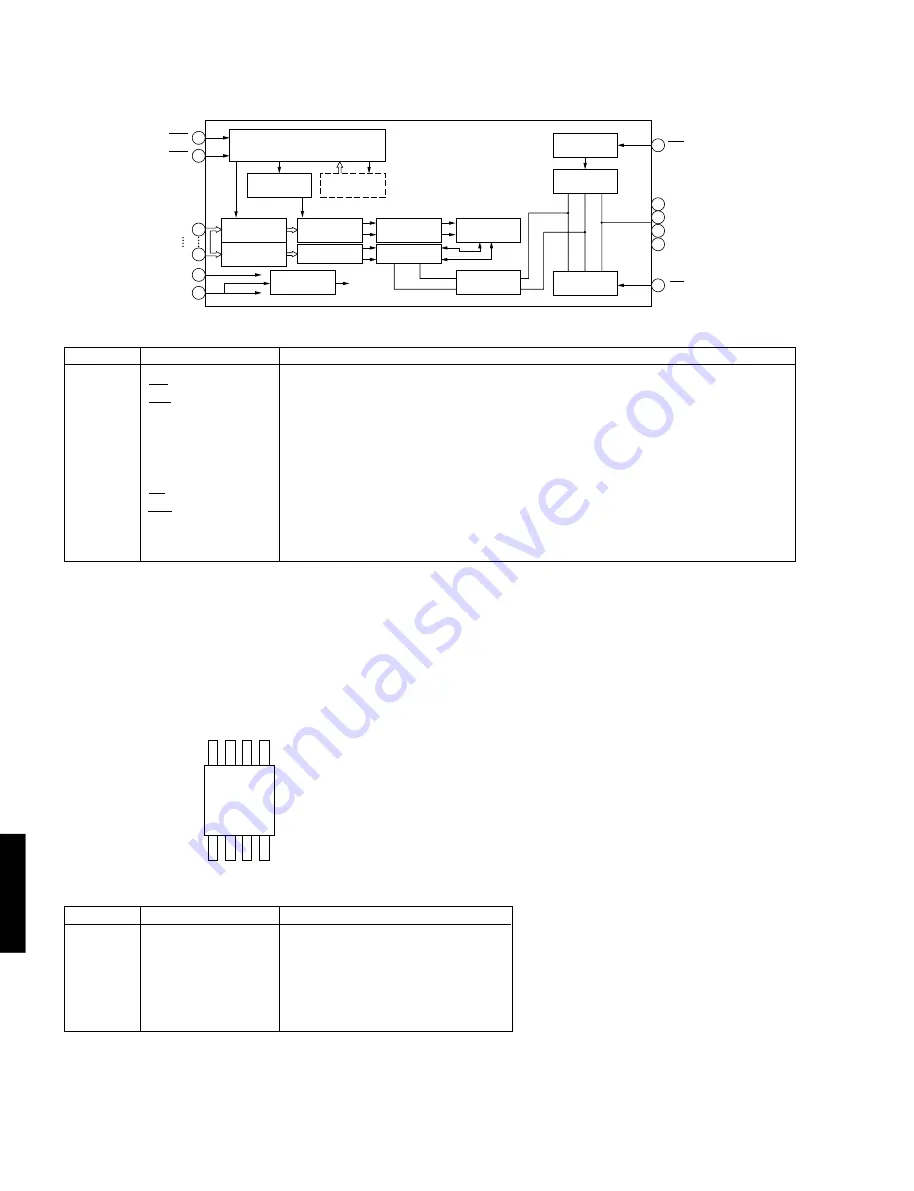
Pin No.
Name
Function
1, 2
DQ0, DQ1
Data input/data output
3
WE
Write enable
4
RAS
Low address strobe
5
A9
Address input
6 — 9
A0-A3
Address input
10
VDD
Power supply (3.3V)
11 — 15
A4-A8
Address input
16
OE
Output enable
17
CAS
Column address strobe
18, 19
DQ2, DQ3
Data input/data output
20
Vss
Power supply (0V)
4
RAS
5
17
15
CAS
A0
A9
WE
DQ0~DQ3
20
V
SS
V
BB
17
CAS
Clock Generator
CBR Refresh
Counter
Row Address
Buffer
Memory
Cell
I/O
Selection
Write Clock
Generator
Data Input
Buffer
Data Output
Buffer
Row Address
Buffer
On ChipVBB
Generator
Row Decoder
Column Decoder
Sense Amp.
Word Driver
SELF Refresh
Timer
MN42V4400 only
3
OE
16
2
18
19
1
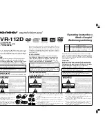
Pin No.
Name
Function
1 — 3
A0 — A2
Device address
4
VSS
Ground
5
SDA
Serial data input/output
6
SCL
Serial clock input
7
WP
Write protect
8
VCC
Power supply
1
2
3
4
8
7
6
5
A0
A1
A2
VSS
VCC
WP
SCL
SDA
IC1202 : IX2474AF
4M Bit D-RAM
IC1402 : 58X2402T
EEPROM
Summary of Contents for MDX-596
Page 59: ...MDX 596 MDX 596 ...


