background image


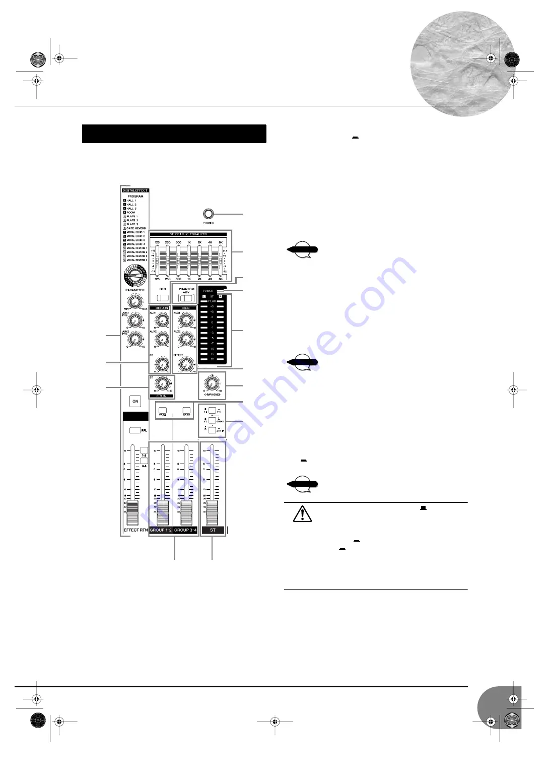
Front & Rear Panels


MG16/6FX


21

1


ST Master Fader


Adjusts the signal level to the ST OUT jacks.

2


GROUP Faders (1-2, 3-4)


Adjust the signal level to the GROUP OUT 1 to 4 jacks.

3


TO ST Switch


If this switch is on (

), the mixer sends the signals processed

by the GROUP faders (

2


) onto the Stereo bus. The Group 1/3

signal go to Stereo L and the Group 2/4 signal go to Stereo R.

4


Master SEND 


• AUX1 and AUX2 Controls


Adjust the level of the signal output to the AUX1 SEND and
AUX2 SEND jacks. 


• Master EFFECT Control


Adjusts the level of the signal on the EFFECT bus. This is the
signal that is output through the EFFECT jack.


These Master SEND controls do not affect the level
of the signal sent from the internal digital effector
onto the Master EFFECT bus.

5


RETURN (AUX1, AUX2, and ST Controls)


• AUX1 and AUX2 Controls


Adjust the level of the mixed L/R signal sent from the
RETURN jacks (L (MONO) and R) to the AUX1 and AUX2
buses.


• ST Control


Adjusts the level of the signal sent from the RETURN jacks
(L (MONO) and R) to the Stereo bus.


If you supply a signal to the RETURN L (MONO)
jack only, the mixer outputs the identical signal to
both the L and R Stereo buses.

6


2TR IN Control


Adjusts the level of the signal sent from the 2TR IN jack to the
Stereo bus.

7


P48 V Switch


This switch toggles phantom power on and off. If you set the
switch on, the mixer supplies power to all channels that provide
MIC input jacks (CHs 1–8, 9/10, 11/12). Set this switch on
(

) when using one or more condenser microphones. 


When this switch is on, the mixer supplies DC +48 V
power to pins 2 and 3 of all XLR-type jacks.


• Be sure to leave this switch off (

) when you are

not using phantom power. Humming or damage
may result if you connect to an unbalanced device
or to an ungrounded transformer while this switch
is on (

). But note that the switch may be left on

(

)  without problem when connecting to bal-

anced dynamic microphones.

• To avoid damage to speakers, be sure to turn off

amplifiers (or powered speakers) before turning this


switch on or off. 


Master Control Section

C

0

9

5

D

6

7

8

3

2

1

4

B

A

NOTE

NOTE

NOTE


MG16-6FX.fm  Page 21  Thursday, December 11, 2003  9:15 AM

Summary of Contents for MG 6FX

Page 1: ...MIXING CONSOLE Owner s Manual Making the Most Of Your Mixer Pages 6 to 18 E MG16 6FX book Page 1 Saturday January 25 2003 10 13 AM ...

Page 2: ...s unit and AC adaptor be dropped or the cabinet be damaged turn the power switch off remove the power plug from the AC outlet and contact your dealer If you continue using the unit without heeding this instruction fire or electrical shock may result If you notice any abnormality such as smoke odor or noise or if a foreign object or liquid gets inside the unit turn it off imme diately Remove the po...

Page 3: ...t neither core is connected to the earth terminal of the three pin plug 1 IMPORTANT NOTICE DO NOT MODIFY THIS UNIT This product when installed as indicated in the instructions con tained in this manual meets FCC requirements Modifications not expressly approved by Yamaha may void your authority granted by the FCC to use the product 2 IMPORTANT When connecting this product to accessories and or ano...

Page 4: ... enables easy connection to condenser microphones that run on external power The mixer provides channel specific INSERT I O jacks for input channels 1 to 8 These jacks make it possible to insert different effectors into different channels Input channels 1 to 8 9 10 and 11 12 are each equipped with both an XLR mic input jack and a TRS phone type line jack Input channels 13 14 and 15 16 are each equ...

Page 5: ... the adaptor from the outlet when not using the mixer or when there are lightning storms in the area To avoid generating unwanted noise make sure there is adequate distance between the power adaptor and the mixer Press the mixer s power switch to the ON position When you are ready to turn the power off press the power switch to the STANDBY position Note that trace current continues to flow while t...

Page 6: ...e the controls and away you go right Well if you ve done this before you won t have any problems but if this is the first time you ve ever used a mixer you might want to read through this little tutorial and pick up a few basics that will help you get better performance and make better mixes MG16 6FX book Page 6 Saturday January 25 2003 10 13 AM ...

Page 7: ...gear The Versatile Phone Jack The name phone jack arose simply because this configuration was first used in telephone switchboards Phone jacks can be tricky because you can t always tell what type of signal they re designed to handle just by looking at them It could be unbalanced mono unbalanced stereo balanced mono or an insert patch point The connector s label will usually tell you what type of ...

Page 8: ...g line level runs The ambient electromagnetic noise level will be the ultimate deciding factor but balanced is best How Do Balanced Lines Reject Noise Skip this section if technical details make you queasy Balanced lines work on the principle of phase cancellation if you add two identical signals out of phase i e one signal is inverted so its peaks coincide with the troughs in the other signal the...

Page 9: ...fessional audio gear usually has line inputs and outputs with a nominal level of 4 dB You should always feed 10 dB inputs with a 10 dB signal If you feed a 4 dB signal into a 10 dB input you are likely to overload the input You should always feed 4 dB inputs with a 4 dB signal A 10 dB signal is too small for a 4 dB input and will result in less than optimum performance Many professional and semi p...

Page 10: ... and treble con trols or a full blown 4 band parametric EQ When boost is applied the EQ stage also has gain You can actually overload the input channel by applying too much EQ boost It s usually better to cut than boost 3 Channel Peak LED Fader The channel peak LED is your most valuable tool for setting the input gain control for optimum performance Note that it is located after the head amp and E...

Page 11: ... mind is that the amount of noise added by each stage is usually not dependent to any significant degree on the level of the audio signal passing through the circuit This means that the bigger the desired signal the smaller the added noise will be in relation to it In tech speak this gives us a better signal to noise ratio often abbreviated as S N ratio All of this leads to the following basic rul...

Page 12: ...l depend on the dynamic range of your program material 1 Start by setting all level controls to their minimum master fad ers group faders if provided channel faders and input gain controls Also make sure that no EQ is applied no boost or cut and that all effects and dynamic processors included in the system are defeated or bypassed 2 Apply the source signal to each channel one at a time have singe...

Page 13: ...re post A pre fader signal is taken from a point before the channel fader so the send level is affected only by the AUX send level control and not by the channel fader Pre fader sends are most commonly used to provide monitor mixes A post fader signal is taken from a point after the channel fader so its level will be affected by both the AUX send level control and the channel fader Post fader send...

Page 14: ...p buses usually also have their own outputs so you can send the group signal to a different external destination from the main mix Channel faders Assigned to Group Controlled As a Group Stereo Master Fader Group Fader Channel faders Assigned to Stereo Controlled Individually A group of channels whose levels need to maintain the same relationship a drum mix for example can be assigned to a group bu...

Page 15: ...lthough they can be used with just about any type of in out processor Channel insert jacks must be used with a special insert cable that has a TRS phone jack on one end and mono phone jacks on the split Y end One of the mono phone jacks carries the send signal to be fed to the input of the external processor and the other carries the return signal from the output of the pro cessor Channel Fader Wh...

Page 16: ...ments What you add next will depend on the type of material you are working with and your approach to it If the vocals are backed by a piano trio and the song is a ballad for example you might want to bring in the piano next and get the vocal piano relationship just right then bring in the bass and drums to support the overall sound Example2 Funky R B Groove The approach will be totally different ...

Page 17: ...ncy ranges that you don t really perceive as musical sound but which can interfere with the clarity of other instruments in these ranges You can basically turn the low EQ on cymbal channels all the way down without changing the way they sound in the mix You ll hear the difference however in the way the mix sounds more spacious and instruments in the lower ranges will have better definition Surpris...

Page 18: ...ant to come through in your mix If you find yourself hearing more high end reverb than mix detail try reducing the brightness of the reverb sound This will allow you to get full bod ied ambience without compromising clarity Reverb Level It s amazing how quickly your ears can lose per spective and fool you into believing that a totally washed out mix sounds perfectly fine To avoid falling into this...

Page 19: ...alizer adjusts the channel s high mid and low frequency bands Setting the knob to the position produces a flat frequency response Turning the knob to the right boosts the corresponding frequency band while turning to the left cuts the band The following table shows the EQ type base frequency and maximum cut boost for each of the three bands Stereo channels CHs 9 10 11 12 13 14 15 16 This four band...

Page 20: ...roup 1 2 3 4 buses or on the Stereo L and R buses The BAL control knob sets the balance between left and right channels Signals into to the L input odd channel feed to the Group 1 3 bus or to the Stereo L bus signals into the R input even channel feed to the Group 2 4 bus or the Stereo R bus On channels where this knob provides both PAN and BAL controls 9 10 and 11 12 the knob oper ates as a PAN c...

Page 21: ...nt from the RETURN jacks L MONO and R to the Stereo bus If you supply a signal to the RETURN L MONO jack only the mixer outputs the identical signal to both the L and R Stereo buses 6 2TR IN Control Adjusts the level of the signal sent from the 2TR IN jack to the Stereo bus 7 PHANTOM 48 V Switch This switch toggles phantom power on and off If you set the switch on the mixer supplies power to all c...

Page 22: ...UT jacks The equalizer is effective only if the GEQ switch is set on The equalizer cuts or boosts each band 125 250 500 1k 2k 4k and 8k Hz over a range of 12 dB C PHONES Jack Connector for headphones This is a balanced stereo phone type output jack The signal monitored by these jacks is selected by the Level Meter Signal switches and the channel PFL switches D DIGITAL EFFECT PROGRAM Dial Selects t...

Page 23: ... jack types are provided phone type CHs 9 10 to 15 16 and RCA pin type CHs 13 14 15 16 Use these jacks to input stereo signals inputting the L signal s to the odd numbered channel s and the R signal s to the even numbered channel s Where a channel provides both a phone jack and an RCA pin jack you may use either one of these jacks but you may not use both at the same time Please connect to only of...

Page 24: ...n external recorder you can record the same signal that is being output from the ST OUT jacks The mixer s ST Master Fader does not operate on the signal output from these jacks Be sure to make appropriate level adjustments at the external recording device 0 2TR IN Jacks These unbalanced RCA pin type input jacks are used to input a stereo sound source Use these jacks when you want to connect a ster...

Page 25: ...use either one of these jacks but you may not use both at the same time Please connect to only one of these jacks on each channel 3 To avoid causing damage to speakers power up the devices in the following order Peripheral devices mixer power amps or powered speakers When shutting the system down turn off the power in the opposite order Power amps powered speak ers mixer peripheral devices Home Re...

Page 26: ...r Speakers Internal Power Amp Effector Synthesizer Effector Bass Guitar CD Cassette or DAT Recorder Microphones Headphones Guitar Main Speakers External Example of Speaker Arrangement Audience External Stage Internal Drums CD Player Power Amp MG16 6FX book Page 26 Saturday January 25 2003 10 13 AM ...

Page 27: ...them into place again using the same screws 3 Mount the unit into the rack and fasten it into place If you wish you may move the left support to the right side and the right support to the left side as shown in the drawing Do not install the mixer near power amps or other heat generating devices Rack Mounting NOTE MG16 6FX book Page 27 Saturday January 25 2003 10 13 AM ...

Page 28: ... 47 dB ST CH LINE INPUT AUX SEND PRE 57 dB ST CH LINE INPUT AUX SEND POST EFFECT SEND 34 dB ST CH INPUT GROUP OUT ST OUT ST to ST 16 dB AUX RETURN ST OUT 9 dB AUX RETURN AUX SEND 27 8 dB 2TR INPUT ST OUT Monaural Stereo Input Gain Control 44 dB variable Monaural Stereo High Pass Filter 80 Hz 12 dB octave Crosstalk 1 kHz 70 dB between input channels 70 dB between input output channels CH INPUT Mona...

Page 29: ... 3 31 type balanced 16 36 dBu 12 3 mV 16 dBu 123 mV 10 dBu 245 mV ST CH LINE INPUT CH9 L CH10 R CH11 L CH12 R 34 10 kΩ 600 Ω line 54 dBu 1 55 mV 34 dBu 15 5 mV 14 dBu 155 mV Phone jack unbalanced 10 10 dBu 245 mV 10 dBu 2 45 V 30 dBu 24 5 V ST CH INPUT CH13 L CH14 R CH15 L CH16 R 10 kΩ 600 Ω line 30 dBu 24 5 mV 10 dBu 245 mV 10 dBu 2 45 V Phone jack unbalanced RCA pin jack CH INSERT IN CHs 1 to 8 ...

Page 30: ...Appendix MG16 6FX 30 Dimensional Diagrams 393 31 5 309 6 D 416 6 H 108 101 3 3 W 423 428 27 5 480 When mounted on rack Unit mm MG16 6FX book Page 30 Saturday January 25 2003 10 13 AM ...

Page 31: ...Appendix MG16 6FX 31 Block Diagram and Level Diagram MG16 6FX book Page 31 Saturday January 25 2003 10 13 AM ...

Page 32: ... 8888 SWEDEN Yamaha Scandinavia AB J A Wettergrens Gata 1 Box 30053 S 400 43 Göteborg Sweden Tel 031 89 34 00 DENMARK YS Copenhagen Liaison Office Generatorvej 8B DK 2730 Herlev Denmark Tel 44 92 49 00 NORWAY Norsk filial av Yamaha Scandinavia AB Grini Næringspark 1 N 1345 Østerås Norway Tel 67 16 77 70 OTHER EUROPEAN COUNTRIES Yamaha Music Central Europe GmbH Siemensstraße 22 34 25462 Rellingen G...

Reviews: