
Using the Compressor
MGP32X/MGP24X Owner’s Manual
32
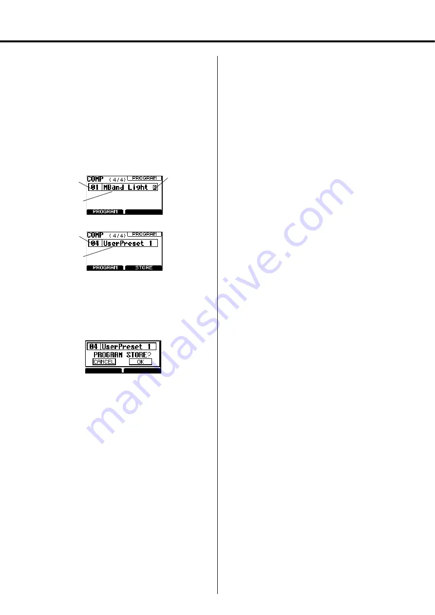
Calling up/saving the compressor pro-
gram
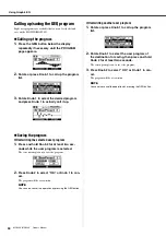
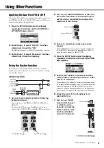
1.
Press the COMP button below the display
repeatedly if necessary until the (4/4) PRO-
GRAM page appears.
2.
Rotate or press Knob 1 to display the program
list.
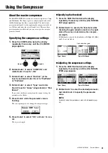
3.
Rotate Knob 1 to select the desired program,
and press Knob 1 again to call it up.
Saving the user program
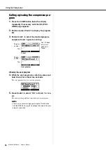
4.
While the user program is called up, press and
hold Knob 2 for at least two seconds.
The screen prompts you to save the program.
5.
Press Knob 2 to select “OK,” or Knob 1 to can-
cel.
The current setting will be overwritten as a user program.
NOTE
• You can also cancel saving by pressing the COMP button.
• Use the MGP Editor (
6) to change the name of the user
program as desired.
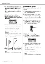
Program
number
Preset
User program
The “R” (Read
only) mark
appears for
Preset.
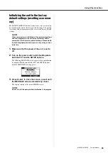
Program
number
Title
Title


