background image

MGP32X/MGP24X     Owner’s Manual

6

Introduction

Main features

D-PRE (Discrete Class-A MIC preamp)

Mono input channels are equipped with Class-A discrete micro-
phone preamplifiers. The head amplifier features an inverted Dar-
lington circuit* used in high-end audio devices, and reproduces 
low frequencies with exceptionally musical characteristics as 
well as sustained high frequencies. Independent toggle switching 
of +48V phantom power and 26dB (pad) on each channel.

Inverted Darlington circuit:

 An amplifying method for elimi-

nating the nonlinear characteristics of the amplifier element 
and suppressing the distortion. The circuit features highly 
musical phase characteristics.

X-pressive EQ

The shelving EQ (low/high) on the mono input channels features 
Xpressive EQ, which effectively models analog EQ utilizing 
Yamaha’s famed VCM (Virtual Circuitry Modeling) technology. 
We analyzed vintage EQ analog circuits and redesigned the tech-
nology specifically for the MGP to create an EQ with exception-
ally musical characteristics. Furthermore, the cutoff frequency 
can also be adjusted, enhancing use of the EQ in sound reinforce-
ment applications, and extending the sonic control range of the 
mixer.

USB device recorder

A USB device recorder is built into the mixer for recording mixed 
audio to a USB device as an audio file, and for playing back 
music saved in the USB device by assigning it to the desired 
channel output or bus output. Supported file formats are MP3 
(MPEG-1 Audio Layer-3) and WAV for recording and MP3, 
WAV, and AAC for playback.

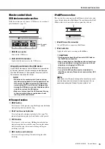
Stereo master – COMP and GEQ

The stereo master is equipped with a compressor (COMP) or 
multiband compressor that adjusts the sound pressure of the out-
put signal, and with a graphic equalizer (GEQ) that adjusts sound 
quality such as feedback.

Digital effects — REV-X and SPX

Two powerful digital effect blocks are built into the mixer: REV-
X (8 types) and SPX (16 types). REV-X gives you a high-density, 
richly reverberant sound ambience, with smooth attenuation, 
spread and depth that work together to enhance the original 
sound. The versatile SPX block features a variety of effect appli-
cations, such as reverb, delay, and modulation effects, along with 
complex combinations of multiple effects.

Convenient, practical functions for events – 
Ducker, Leveler, and Stereo Image

The mixer features three exceptionally convenient features for the 
stereo input channels: Ducker, Leveler and Stereo Image. The 
ducker function automatically lowers the level of background 
music to accommodate the voice of an announcer coming in on 
another channel. The leveler function automatically maintains a 
consistent sound volume, even when using sound sources that 
have different mastering levels. Stereo image narrows the pan 
balance of the stereo sound source, and changes stereo signals to 
mono. This is useful in restaurants and other spaces where the left 
and right speakers are distantly positioned, or when you input 
accompaniment sound to the left channel and vocal sound to the 
right and want a more natural stereo image.

USB port for playing and charging your iPod/
iPhone

Digital audio output from the iPod/iPhone can be directly input to 
the unit, and the iPod/iPhone can be charged while connected.
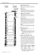
About the models

The MGP32X and MGP24X feature a different number of mon-
aural input channels and COMP control knobs. The MGP32X has 
24 monaural input channels and the MGP24X has 16. The 
MGP32X is equipped with 16 COMP control knobs for channels 
9-24 and the MGP24X with 8 COMP control knobs for channels 
9-16.

Conventions in this manual

• Whenever there is a different number of channels or a different 

channel number for the same function between the MGP32X 
and the MGP24X, the number that applies only to the MGP24X 
model is enclosed in curly brackets { }. For example, “CH1-24 
{CH1-16}” means channels 1-24 for the MGP32X and chan-
nels 1-16 for the MGP24X.

*  “CH” is an abbreviation for channel.

• Control knobs on the panel are called “knobs.” Some knobs 

rotate from a minimum value to a maximum value, while others 
rotate endlessly.

MGP Editor

MGP Editor is a free software application that gives you addi-
tional control of your MGP mixer’s DSP settings via your iPhone, 
iPod touch, and iPad. See the following web site to download the 
application. 

http://www.yamahaproaudio.com/global/en/products/periph-
erals/applications/mgp_editor/

Included Accessories

• AC Power Cord
• Owner’s manual (this book)

Thank you for purchasing the Yamaha MGP32X/MGP24X 
mixing console.
Please read this manual thoroughly to make the best use of 
the mixing console for the longest possible period of time. 
After reading this manual, please keep it available for future 
reference.

Summary of Contents for MGP32X

Page 1: ...EN Owner s Manual PRECAUTIONS pages 4 to 5 Setup pages 7 to 9 Troubleshooting pages 40 to 41...

Page 2: ...g type plug A polarized plug has two blades with one wider than the other A grounding type plug has two blades and a third grounding prong The wide blade or the third prong are provided for your safet...

Page 3: ...of the screen 25 Using Effects FX 26 Applying effects 26 Detailed effect settings 26 Applying two effects simultaneously 27 Displaying FX1 and FX2 together 27 Using Graphic EQ 28 About the graphic EQ...

Page 4: ...hen have the device inspected by Yamaha service personnel The power cord or plug becomes frayed or damaged It emits unusual smells or smoke Some object has been dropped into the instrument There is a...

Page 5: ...e condensation has completely dried out Avoid setting all equalizer controls and faders to their maximum Depending on the condition of the connected devices doing so may cause feedback and may damage...

Page 6: ...enient practical functions for events Ducker Leveler and Stereo Image The mixer features three exceptionally convenient features for the stereo input channels Ducker Leveler and Stereo Image The ducke...

Page 7: ...ponding peak indicators flash briefly at the highest peak levels NOTE To use the level meter to get a more accurate reading of the incoming signal level turn on the channel PFL switch Adjust the GAIN...

Page 8: ...yer voice Computer Audio interface DJ mixer Synthesizer Power amp Powered speakers Microphone CH24 CH16 for MC Setup example Lamp Yamaha LA 1L CD player Powered monitor speakers Foyer etc Stage Speake...

Page 9: ...Drum Bass Rear panel The illustrations show the panel of the MGP32X Top panel CAUTION When using a condenser microphone set the 48V phantom switch to ON page 11 If electric guitars and basses can be c...

Page 10: ...ge 16 SEND MASTER section page 18 MATRIX section page 18 USB IN iPod IN section page 19 PHONES MONITOR section page 19 TALKBACK section page 20 STEREO master section page 21 MONO master section page 2...

Page 11: ...on Turn the mixer s output controls STEREO master and GROUP faders all the way down when turning phan tom power on off e GAIN knob Adjusts the sensitivity of the input signal Monaural channels have a...

Page 12: ...36 0 STEREO IMAGE switch Selects the type of output signal for the input stereo signal MONO Mono signal BLEND Stereo signal in which left and right inputs are mixed at a certain percentage for a more...

Page 13: ...ono channels BAL knob Stereo channels These knobs set the stereo pan position and determine the volume balance between left and right When the channels are panned hard left or hard right sound is hear...

Page 14: ...Controls and Connectors MGP32X MGP24X Owner s Manual 14 AUX1 AUX2 ST 1 2 3 4 AUX3 AUX4 Mono Channel Stereo Channel...

Page 15: ...nect an iPod iPhone w iPod indicator Lights when the unit is accessing an iPod iPhone CAUTION Use the genuine Apple Dock Connector USB Cable for the iPod iPhone connection When connecting to an iPod i...

Page 16: ...display to adjust the contrast of the display and to set the ducker and the leveler Meter section Use these meters to view various signal levels the levels to the STEREO OUT L R jacks the PFL and AFL...

Page 17: ...ntil you get the timing right The TAP indicator flashes in sync with the delay time when DELAY or SINGLE DELAY is selected NOTE Adjust the average interval within range of the variable delay time See...

Page 18: ...n off all PFL switches If the PFL preferred is enabled the AFL indicator does not light even if the AFL switch is pressed MATRIX section This section adjusts the levels and controls the output of sign...

Page 19: ...signal output from the con nected iPod iPhone TO STEREO Sends to the STEREO L R bus TO MONITOR Sends to the MONITOR OUT jacks and PHONES jack NOTE CH29 30 31 32 CH21 22 23 24 can be selected as the d...

Page 20: ...e the ST and AFL switches to selectively send these groups to the STEREO and AFL buses q PAN knob Determines how the signal from the GROUP 1 4 buses is posi tioned on the STEREO L R buses when turning...

Page 21: ...usts the level of the signal output in mono from the STE REO bus to the MONO OUT jack STEREO master section This section adjusts the level of the main output from the STE REO bus q ON switch Turning t...

Page 22: ...in jack line inputs NOTE On any given channel you may use either a phone or RCA pin jack but not both Master I O connectors section e MATRIX OUT 1 2 These are impedance balanced TRS phone jacks These...

Page 23: ...multi track recorder external mixer or similar device 0 STEREO OUT L R These are balanced XLR and TRS output jacks that output the mixed stereo signal They output the signal adjusted by the STEREO mas...

Page 24: ...ay Also the GR Gain reduction indicator displays the status of the signal when compressed highlighted or not compressed normal dis play t iPod status Displays the connected highlighted or disconnected...

Page 25: ...call up the list Rotate Knob 1 to select the desired program title and then press Knob 1 to actually select it Exiting the screen To return to the HOME screen from the current screen press the HOME bu...

Page 26: ...TN or FX2 RTN fader to the 0 posi tion 8 Rotate Knob 2 to adjust the effect depth The value on the lower right side of the screen will change on the display NOTE If 06 VOCAL ECHO 07 KARAOKE ECHO 08 DE...

Page 27: ...n conveniently be displayed on one screen together You can select the program and operate the parameter on the same screen 1 Press the FX1 button and the FX2 button together Both FX1 and FX2 screens a...

Page 28: ...atible 5 Press Knob 2 to select OK or Knob 1 to can cel The GEQ type will be changed Setting the frequency and gain 1 Press the GEQ button below the display repeatedly if necessary until the EDIT page...

Page 29: ...ob 2 again to select OK or Knob 1 to cancel The link is disabled Finding and removing feedback Using the offset gain lets you check the feedback point in advance and feedback can be reduced by correct...

Page 30: ...ogram 1 Press and hold Knob 2 for at least two sec onds while the user program is selected The screen prompts you to save the program 2 Press Knob 2 to select OK or Knob 1 to can cel The program will...

Page 31: ...gle band or Mul tiband If you select a different setting from the current setting the parameter value flashes 5 Press Knob 2 while the parameter value is flashing The screen prompts you to change the...

Page 32: ...ain to call it up Saving the user program 4 While the user program is called up press and hold Knob 2 for at least two seconds The screen prompts you to save the program 5 Press Knob 2 to select OK or...

Page 33: ...ee the operation of all USB devices It is recommended that you check the opera tion of the USB device beforehand USB device format FAT32 format is supported The maximum size for one file is 2GB Suppor...

Page 34: ...unction is not installed in the unit the date of the file is fixed e Rotate Knob 1 to select the recorded song and then press Knob 1 to confirm it Playback starts Playing back songs from a USB device...

Page 35: ...ary until the USB 1 3 PLAYER page appears 2 Rotate or press Knob 1 to display the title list When you select the line of the folder and press Knob 1 the content of the folder appears Selecting the lin...

Page 36: ...tting to channels 31 32 23 24 Use the channel fader to adjust the volume NOTE Avoid adjusting both outputs at the same time because of the delay of the signal path 5 Operate the iPod or iPhone to stop...

Page 37: ...of the chan nel to which the device is connected in step 1 and then rotate the GAIN knob to adjust the input level of the channel 3 Connect a microphone to the input source channel For the MGP32X unit...

Page 38: ...tically maintains a consistent sound volume even when using sound sources that have different mas tering levels 1 Connect a USB device or an audio player such as an iPod iPhone to the unit 2 If you co...

Page 39: ...t user memory will be overwritten with the factory default settings Proceed with the following operation only if you are very sure you want to do this 1 Make sure that the power of the unit is set to...

Page 40: ...evels Are two different instruments connected to the XLR type and phone jacks or to the phone and RCA pin jacks on one channel Make sure to connect to only one of these jacks on each channel Are micro...

Page 41: ...a stereo signal is input the left and right vol ume is different Is the pan knob set to the center position If it is located in the center try swapping the connections If the lesser greater volume sig...

Page 42: ...t Recording Recording did not start due to the status of the USB device Current Exceeded iPod The device connected to the iPod iPhone IN connecter exceeded current Disconnect the device Current Exceed...

Page 43: ...f a small space room 03 PLATE Reverb simulating a metal plate producing a more hard edged sound 04 LARGE STAGE Reverb simulating a large stage 05 SMALL STAGE Reverb simulating a small stage 06 VOCAL E...

Page 44: ...unt Parameter Range Description Delay 30 0 710 0 ms VOCAL ECHO Delay time VOCAL ECHO R channel the value in the left column plus 33 0 ms KARAOKE ECHO R channel the value in the left column plus 65 0 m...

Page 45: ...n once the trigger signal level drops below the threshold Out Level 12 to 12 dB This sets the compressor s output signal level Parameter Range Description L M Xover 21 2 Hz 4 0 kHz Low mid crossover f...

Page 46: ...Hot Pin 3 Cold XLR 3 31 XLR 3 32 connector TALKBACK Pin 1 Ground Pin 2 Hot Pin 3 Cold XLR 3 31 connector LAMP Pin 1 NC Pin 2 NC Pin 3 Ground Pin 4 12 V XLR 4 31 connector INPUT B mono channels STEREO...

Page 47: ...MGP32X MGP24X Owner s Manual 47 Appendix Dimensions MGP32X MGP24X Unit mm 1027 169 819 169 565 565...

Page 48: ...Hz to 20 kHz GAIN knob min Refer to the nominal output level 1 kHz 0 5 1 0 dB Total Harmonic Distortion THD N STEREO OUT GAIN knob min output level 14 dBu 20 Hz to 20 kHz 0 02 Noise 1 CH INPUT MIC EI...

Page 49: ...dBu 123 mV 4 dBu 1 23 V 26 dB 34 dB 600 Lines 54 dBu 1 55 mV 34 dBu 15 5 mV 14 dBu 155 mV Phone Jack 3 10 dB 10 dBu 245 mV 10 dBu 2 45 V 30 dBu 24 5 V ST CH Input MGP32X 25 32 MGP24X 17 24 34 dB 10 k...

Page 50: ...ONIC 03 PLATE 06 VOCAL ECHO 09 SINGLE DELAY 12 PHASER 15 DOUBLER GEQ STEREO OUT L R TYPE 14BandGEQ Flex9GEQ 8 User Programs COMP STEREO OUT L R TYPE Comp MultiBand 3 Preset Programs 5 User Programs US...

Page 51: ...6 Headphones 7 19 High Pass Filter 11 I Initializing 39 Instruments 7 iPod iPhone 15 36 J Jack List 46 L Leveler 6 12 38 Link 29 List 25 Low Pass Filter 37 LPF Low Pass Filter 37 M Maintenance 5 MATRI...

Page 52: ...Appendix MGP32X MGP24X Owner s Manual 52 Block Diagram and Level Diagram...

Page 53: ...MGP32X MGP24X Owner s Manual 53 Appendix...

Page 54: ...MGP32X MGP24X Owner s Manual 54...

Page 55: ...r its subsidiaries FCC INFORMATION U S A weee_eu_en_01 Information for Users on Collection and Disposal of Old Equipment This symbol on the products packaging and or accompanying documents means that...

Page 56: ...L Yamaha Music Europe GmbH Ib rica Sucursal en Espa a Ctra de la Coruna km 17 200 28230 Las Rozas Madrid Spain Tel 34 902 39 8888 GREECE Philippos Nakas S A The Music House 147 Skiathou Street 112 55...

Reviews: