43
MODX6/MODX7
LCD display
Test items and judging conditions
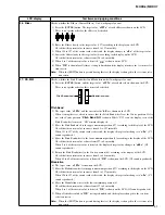
11 : USB (to DEVICE)
Checks whether the USB TO DEVICE terminal works properly or not.
1) Press the [ENTER] button first. “
Insert USB Memory!
” is shown on the LCD.
2) Insert the USB flash drive.
3) Confirm that “
OK
” is shown on the LCD.
4) When OK/NG of the test result is shown, testing is finished and the display is changed to the test
item selection screen.
5) Disconnect the USB flash drive.
12 : USB (to HOST)
Checks whether the USB TO HOST terminal works properly or not.
1) Press the [ENTER] button first. “
Connect USB!
” is shown on the LCD.
2) Connect the USB TO DEVICE terminal and USB TO HOST terminal by using the USB cable.
3) Confirm that “
OK
” is shown on the LCD.
4) When OK/NG of the test result is shown, testing is finished and the display is changed to the test
item selection screen.
5) Disconnect the USB cable.
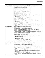
13 : OUTPUT-L (-12dB)
Checks each output level and pitch from the L channel of the jacks.
1) Connect the frequency counter to the PHONES jack at L.
2) Connect the level meter to an output jack.
3) Set the [MASTER VOLUME] control to the maximum position.
4) Press the [ENTER] button to produce the 1kHz sine wave sound. “
ON
” is shown on the LCD.
5) Measure the frequency and confirm that the measured value is 1 kHz ± 0.2Hz.
6) Measure the output level and confirm that the measured values are within the specified range.
[PHONES]
(33
-ohms
load)
PHONES L: -3.8 dBu±2 dB
PHONES R: -62.0 dBu or less
[OUTPUT]
(10k
-ohms
load)
L/MONO : +1.6 dBu±2 dB
R : -72 dBu or less
[OUTPUT]
(10k
-ohms
load)
L/MONO : -4.1 dBu±2 dB
R : Unconnected
7) Set the [MASTER VOLUME] control to the minimum position.
8) Measure the output level and confirm that the measured value is within the specified range.
[OUTPUT]
(10k
-ohms
load)
L/MONO: -72.0 dBu or less
9) Press the [EXIT] button, and testing is finished and the display is changed to the test item selection
screen.
Summary of Contents for MODX6
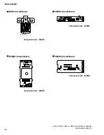
Page 23: ...23 MODX6 MODX7 C C Pattern side DM Circuit Board C C 2NA ZW84620 1...
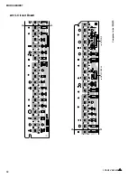
Page 24: ...MODX6 MODX7 24 PNC Circuit Board Component side 2NA ZX42110...
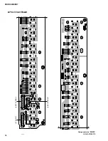
Page 28: ...MODX6 MODX7 28 PNR Circuit Board Component side 2NA ZX42110...
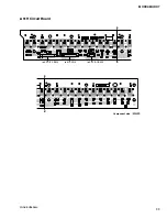
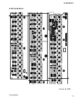
Page 29: ...29 MODX6 MODX7 to PNC CB107 Pattern side PNR Circuit Board 2NA ZX42110...
Page 31: ...31 MODX6 MODX7 TOME4 Circuit Board Component side Pattern side 2NA ZX42110...


