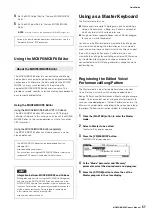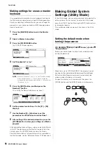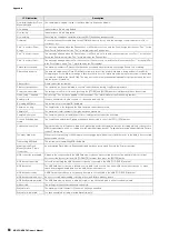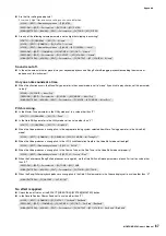
MOXF6/MOXF8 Owner’s Manual
Appendix
71
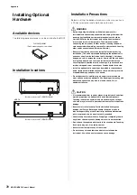
Installing Optional Hardware
FL512M/FL1024M
Configuration
There are two types of the Flash Memory Expansion Module:
FL512M
Features a memory size of 512 MB.
FL1024M
Features a memory size of 1024 MB.
Installation Procedure
1
Turn the power of the MOXF off, and disconnect
the AC power cord. Also, make sure to disconnect
the MOXF from any connected external devices.
2
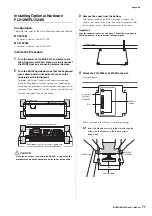
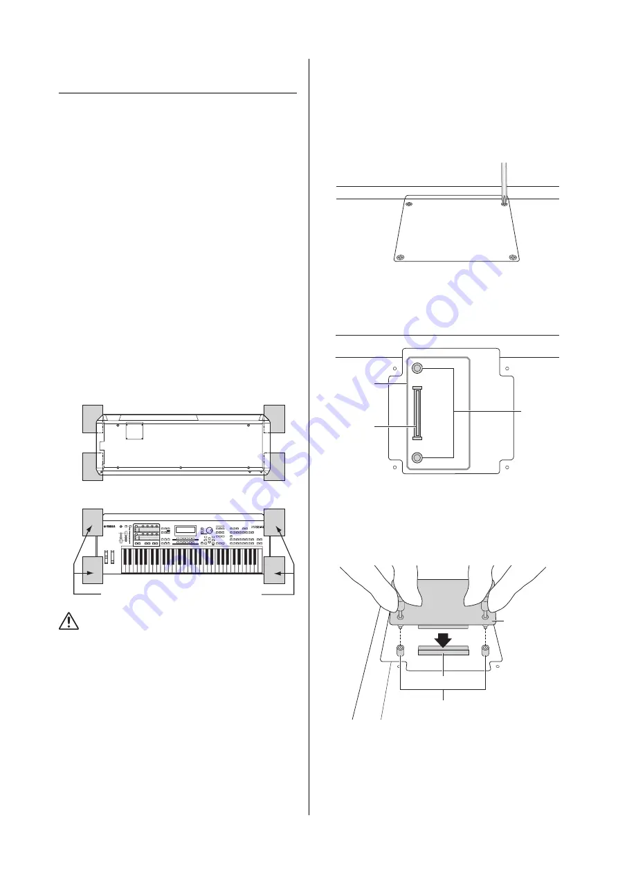
Turn the MOXF upside down so that the keyboard
faces down and you have direct access to the
underside of the instrument.
To protect the Knobs, Wheels and Sliders from damage,
place the keyboard so the four corners are supported by
something that provides sufficient support like magazines or
cushions. Place supports at all four corners, taking care not
to touch the Knobs, Wheels and Sliders.
CAUTION
• Since the instrument—particularly the MOXF8—is very heavy, this
procedure should not be done alone, but by two or three people.
3
Remove the cover from the bottom.
With the rear panel of the MOXF facing you, remove the
screws from the cover by using the Phillips screwdriver. After
removing the screws, slide the cover away to remove it.
Important
Keep the removed screws in a safe place. They will be used when re-
attaching the cover to the instrument after installation.
4
Attach the FL1024M or FL512M to the slot.
As shown below.
Attach the module to the slot via the following steps.
4-1
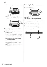
Insert the Module vertically in the slot and align the
screws (on the Module) to the female screws
respectively.
Rear side
View of the keyboard from the bottom
Place supports at all four corners, taking care
not to touch the Knobs, Wheels and Sliders.
Rear side
Bottom
Location for
FL512M/
FL1024M
Slot
Female
screws
Slot
Female screws
Rear side
FL512M/
FL1024M
Summary of Contents for MOXF6
Page 1: ...Owner s Manual EN...
Page 76: ...76 MOXF6 MOXF8 Owner s Manual Memo...
Page 77: ...MOXF6 MOXF8 Owner s Manual 77 Memo...
Page 78: ......

