MOXF6/MOXF8 Reference Manual
Utility Mode
147
1StereoRec........ The audio signal from the A/D INPUT [L]/[R] jacks and the tone generator are output together to the “USB 1/2”
channels of the USB TO [HOST] jack. This mode is for using the 1 stereo channels (2 channels) as output
channels.
DirectMonitorSw A/D In&Part (Direct Monitor Switch A/D Input & Part)
Determines whether or not the audio signal which is output to the external device via the “USB 1/2” channels also
sounds from this instrument (Direct Monitoring). When this is set to “on,” the audio signal which is output via the “USB 1/
2” channels is also output to the OUTPUT [L/MONO]/[R] jacks and [PHONES] jack. The audio signal output to “USB 1/2”
channels varies depending on the “Mode” setting. When “Mode” is set to “VST,” “DirectMonitorSw A/D In” is indicated in
this parameter.
Settings:
off, on
NOTE
When the maximum number of output channels for USB is set to 2 channels, “Mode” is fixed to “1StereoRec.“ For details, see
the [SF1] OUT CH display (
).
DirectMonitorSw Part (Direct Monitor Switch Part)
This parameter is shown only when “Mode” is set to “VST” or “2StereoRec.” Determines whether or not the audio signal
which is output to the external device via the “USB 3/4” channels also sounds from this instrument (Direct Monitoring).
When this is set to “on,” the audio signal which is output via the “USB 3/4” channels is also output to the OUTPUT [L/
MONO]/[R] jacks and [PHONES] jack.
Settings:
off, on
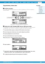
[SF1] OUT CH (Output Channel)
Pressing this button calls up the display which determines whether the maximum number of output channels for USB is
4 channels (2 stereo channels) or 2 channels (1 stereo channel). If transfer of the audio signal between the MOXF6/
MOXF8 and the computer connected to the MOXF6/MOXF8 is compromised or impossible, set this parameter to “2ch.”
This setting reduces the CPU load of the computer, and may resolve the problem. After changing this setting, press the
[ENTER] button, then restart the MOXF6/MOXF8.
NOTICE
After changing this setting and pressing the [ENTER] button, make sure to restart the MOXF6/MOXF8; the instrument will not
operate otherwise. Before restarting, make sure to store any important edited data to prevent it from being inadvertently lost.
[SF6] INFO (Information)
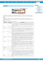
Pressing this button calls up the display which indicates the illustration of the audio connection You can confirm the
“Mode” setting and “DirectMonitor Switch” setting here.
[SF1] CH (Channel)
From this display you can make basic MIDI settings.
BasicRcvCh (Basic Receive Channel)
Determines the MIDI receive channel when this synthesizer is set to single-timbre tone generator mode (Voice/
Performance modes).
Settings:
1 – 16, omni (all channels), off
NOTE
In the multi-timbral tone generator mode (Song/Pattern modes), each Part receives MIDI data according to its assigned MIDI
receive channel ([SONG] or [PATTERN]
[MIXING]
[EDIT]
Part selection
[F1] VOICE
[SF2] MODE
ReceiveCh).
[F6] MIDI

