5-17
ROCKER ARMS AND CAMSHAFT
3. Measure:
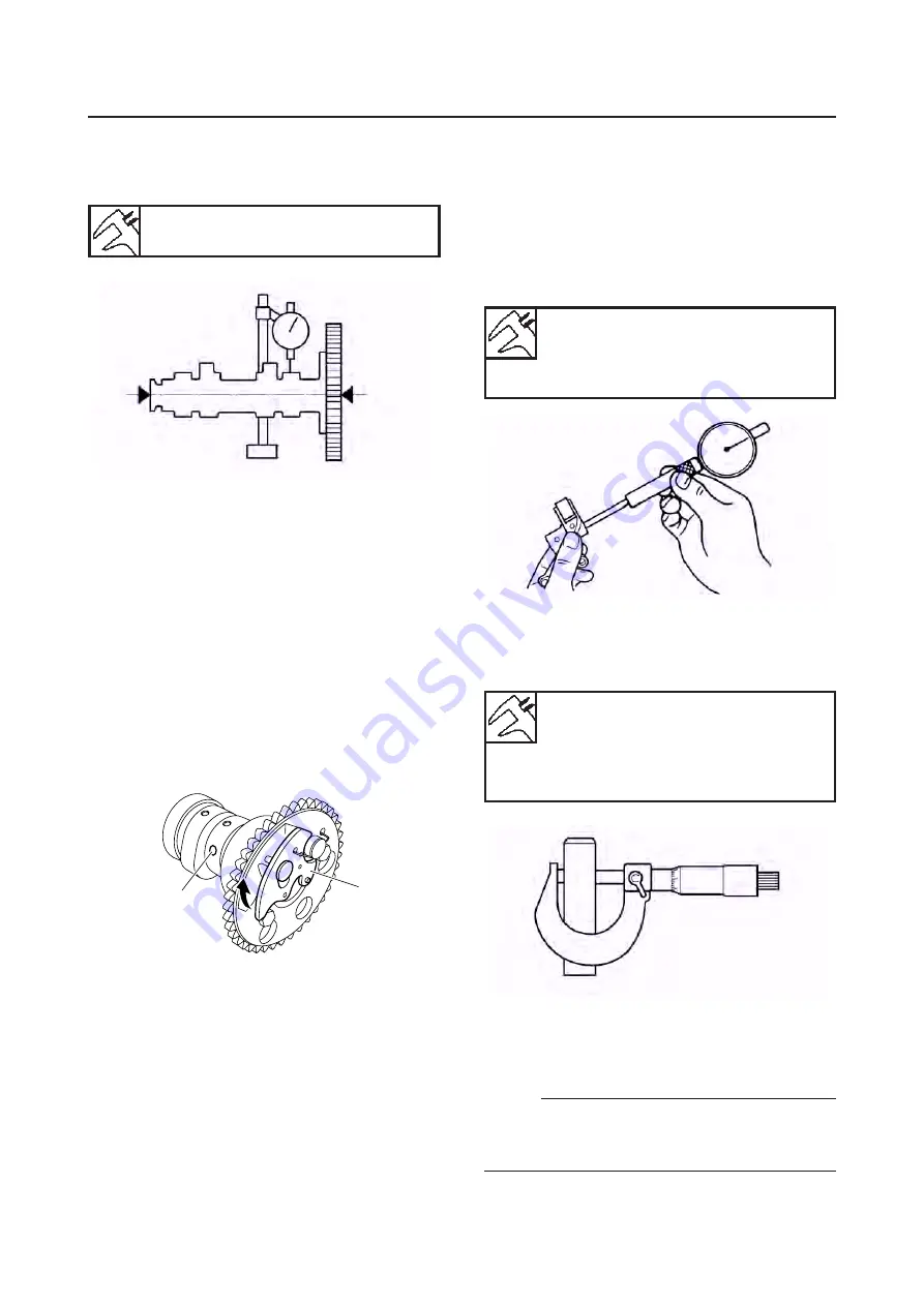
• Camshaft runout
Out of specification
→
Replace.
Camshaft runout limit
0.040 mm (0.0016 in)
CHECKING THE DECOMPRESSION
SYSTEM
a. Check the decompression system with the
camshaft sprocket installed on and the de-
compressor pin installed in the camshaft.
b. Check that the decompressor lever pin “1”
c. Check that the decompressor cam “2”
CHECKING THE ROCKER ARMS AND
ROCKER ARM SHAFTS
The following procedure applies to both of the
rocker arms and rocker arm shafts.
1. Check:
▼▼▼▼▼▼▼▼▼▼▼▼▼▼▼▼▼▼▼▼▼▼▼▼▼▼▼▼▼▼▼▼
▼▼▼▼▼▼▼▼▼▼▼▼▼▼▼▼▼▼▼▼▼▼▼▼▼▼▼▼▼▼▼▼
2. Check:
• Rocker arm shaft
Blue discoloration/excessive wear/pitting/
scratches
→
Replace or check the lubrica-
tion system.
3. Measure:
• Rocker arm inside diameter
Out of specification
→
Replace.
Rocker arm inside diameter
12.000-12.018 mm
(0.4724-0.4731 in)
<Limit>: 12.036 mm (0.4739 in)
Rocker arm shaft outside
diameter
11.981-11.991 mm
(0.4717-0.4721 in)
<Limit>: 11.955 mm (0.4707 in)
4. Measure:
• Rocker arm shaft outside diameter
Out of specification
→
Replace.
5. Calculate:
• Rocker-arm-to-rocker-arm-shaft clearance
NOTE:
Calculate the clearance by subtracting the
rocker arm shaft outside diameter from the
rocker arm inside diameter.
Summary of Contents for MT-03
Page 7: ......
Page 9: ......
Page 25: ......
Page 53: ...2 28 COOLING SYSTEM DIAGRAMS 1 2 3 4 5 6 7 8 9 5 10 11 A B C ...
Page 56: ...2 31 LUBRICATION CHART Pressure feed Splashed scavenge ...
Page 57: ...2 32 LUBRICATION DIAGRAMS LUBRICATION DIAGRAMS A A 1 3 2 2 4 A A A A ...
Page 59: ...2 34 LUBRICATION DIAGRAMS A A A A 3 1 2 3 4 ...
Page 60: ...2 35 LUBRICATION DIAGRAMS 1 Oil delivery pipe 2 2 Oil delivery pipe 1 3 Oil filter 4 Oil pump ...
Page 61: ...2 36 LUBRICATION DIAGRAMS 1 7 2 3 4 5 6 A ...
Page 63: ...2 38 LUBRICATION DIAGRAMS 1 6 5 4 3 2 ...
Page 65: ...2 40 CABLE ROUTING CABLE ROUTING ...
Page 67: ...2 42 CABLE ROUTING ...
Page 69: ...2 44 CABLE ROUTING ...
Page 71: ...2 46 CABLE ROUTING ...
Page 73: ...2 48 CABLE ROUTING ...
Page 75: ...2 50 CABLE ROUTING ...
Page 77: ...2 52 CABLE ROUTING ...
Page 79: ...2 54 CABLE ROUTING ...
Page 81: ...2 56 CABLE ROUTING ...
Page 83: ...2 58 CABLE ROUTING ...
Page 85: ...2 60 CABLE ROUTING ...
Page 87: ......
Page 121: ......
Page 177: ...4 54 FRONT FORK WARNING Make sure the brake hoses are routed prop erly ...
Page 271: ......
Page 273: ......
Page 287: ......
Page 325: ......
Page 339: ...8 12 CHARGING SYSTEM 2 A C magneto 5 Rectifier regulator 7 Battery 8 Main fuse ...
Page 341: ...8 14 CHARGING SYSTEM ...
Page 355: ...8 28 COOLING SYSTEM ...
Page 365: ...8 38 IMMOBILIZER SYSTEM ...
Page 366: ...8 39 ELECTRICAL COMPONENTS EAS27970 ELECTRICAL COMPONENTS ...
Page 368: ...8 41 ELECTRICAL COMPONENTS ...
Page 370: ...8 43 ELECTRICAL COMPONENTS EAS27980 CHECKING THE SWITCHES ...
Page 389: ......
Page 391: ......
Page 397: ...COLOR CODE ...
Page 398: ......
Page 399: ...YAMAHA MOTOR ITALIA S P A ...
Page 400: ...MT 03 2006 WIRING DIAGRAM ...


