5-69
CRANKSHAFT
EAS00408
INSTALLING THE CRANKSHAFT
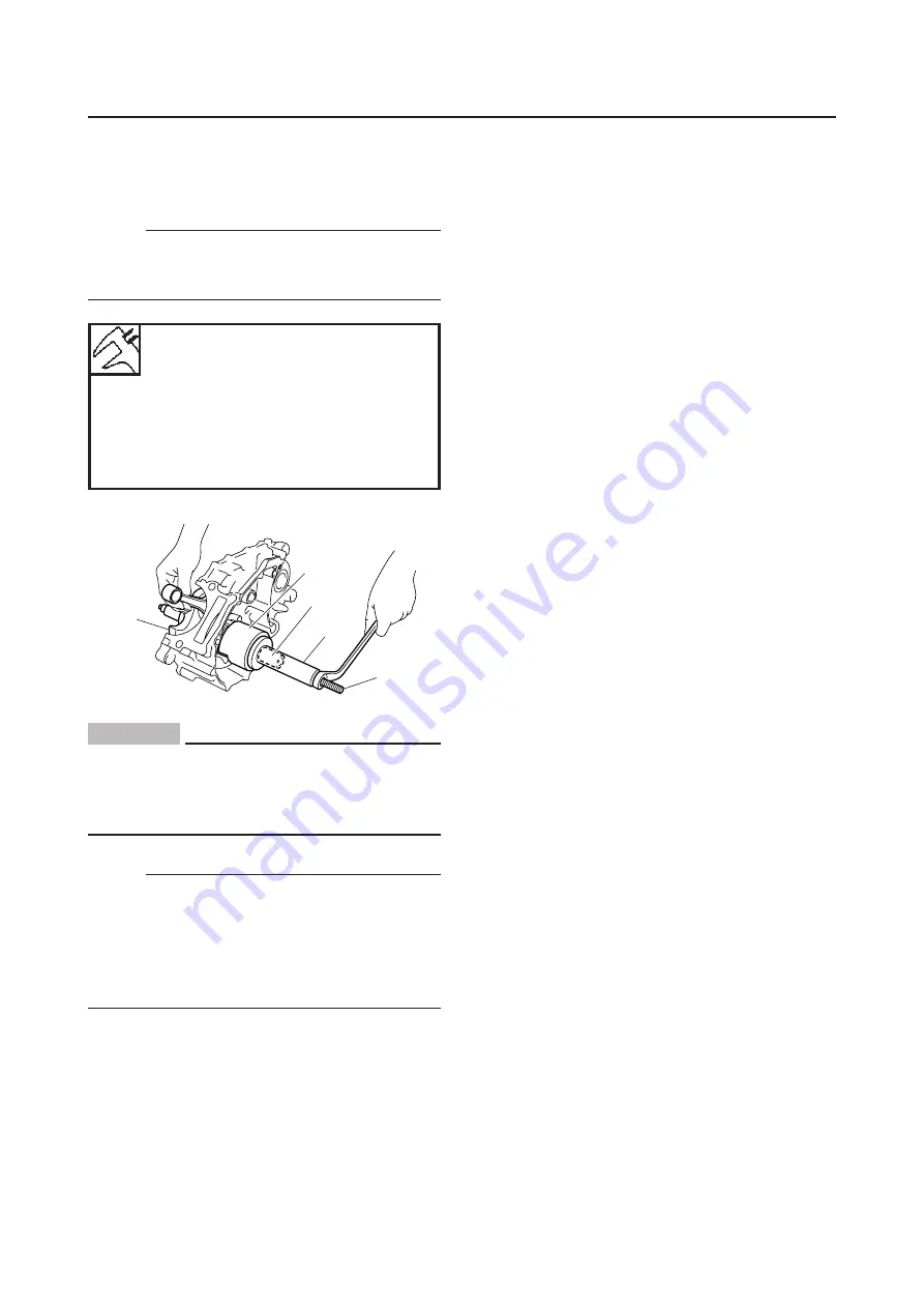
1. Install:
• Crankshaft “1”
NOTE:
Install the crankshaft with the crankshaft in-
staller pot, crankshaft installer bolt, adapter
and spacer (crankshaft installer).
Crankshaft installer pot “2”
90890-01274
Crankshaft installer bolt “3”
90890-01275
Adapter “4”
90890-04130
Spacer (crankshaft installer) “5”
90890-04144
CAUTION:
To avoid scratching the crankshaft and to
ease the installation procedure, lubricate
the oil seal lips with lithium-soap-based
grease and each bearing with engine oil.
NOTE:
Hold the connecting rod at the top dead center
(TDC) on the compression stroke with one
hand while turning the nut of the crankshaft in-
staller bolt with the other. Turn the crankshaft
installer bolt until the crankshaft bottoms
against the bearing.
1
5
4
2
3
Summary of Contents for MT-03
Page 7: ......
Page 9: ......
Page 25: ......
Page 53: ...2 28 COOLING SYSTEM DIAGRAMS 1 2 3 4 5 6 7 8 9 5 10 11 A B C ...
Page 56: ...2 31 LUBRICATION CHART Pressure feed Splashed scavenge ...
Page 57: ...2 32 LUBRICATION DIAGRAMS LUBRICATION DIAGRAMS A A 1 3 2 2 4 A A A A ...
Page 59: ...2 34 LUBRICATION DIAGRAMS A A A A 3 1 2 3 4 ...
Page 60: ...2 35 LUBRICATION DIAGRAMS 1 Oil delivery pipe 2 2 Oil delivery pipe 1 3 Oil filter 4 Oil pump ...
Page 61: ...2 36 LUBRICATION DIAGRAMS 1 7 2 3 4 5 6 A ...
Page 63: ...2 38 LUBRICATION DIAGRAMS 1 6 5 4 3 2 ...
Page 65: ...2 40 CABLE ROUTING CABLE ROUTING ...
Page 67: ...2 42 CABLE ROUTING ...
Page 69: ...2 44 CABLE ROUTING ...
Page 71: ...2 46 CABLE ROUTING ...
Page 73: ...2 48 CABLE ROUTING ...
Page 75: ...2 50 CABLE ROUTING ...
Page 77: ...2 52 CABLE ROUTING ...
Page 79: ...2 54 CABLE ROUTING ...
Page 81: ...2 56 CABLE ROUTING ...
Page 83: ...2 58 CABLE ROUTING ...
Page 85: ...2 60 CABLE ROUTING ...
Page 87: ......
Page 121: ......
Page 177: ...4 54 FRONT FORK WARNING Make sure the brake hoses are routed prop erly ...
Page 271: ......
Page 273: ......
Page 287: ......
Page 325: ......
Page 339: ...8 12 CHARGING SYSTEM 2 A C magneto 5 Rectifier regulator 7 Battery 8 Main fuse ...
Page 341: ...8 14 CHARGING SYSTEM ...
Page 355: ...8 28 COOLING SYSTEM ...
Page 365: ...8 38 IMMOBILIZER SYSTEM ...
Page 366: ...8 39 ELECTRICAL COMPONENTS EAS27970 ELECTRICAL COMPONENTS ...
Page 368: ...8 41 ELECTRICAL COMPONENTS ...
Page 370: ...8 43 ELECTRICAL COMPONENTS EAS27980 CHECKING THE SWITCHES ...
Page 389: ......
Page 391: ......
Page 397: ...COLOR CODE ...
Page 398: ......
Page 399: ...YAMAHA MOTOR ITALIA S P A ...
Page 400: ...MT 03 2006 WIRING DIAGRAM ...


