6-5
THERMOSTAT
EAS00462
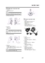
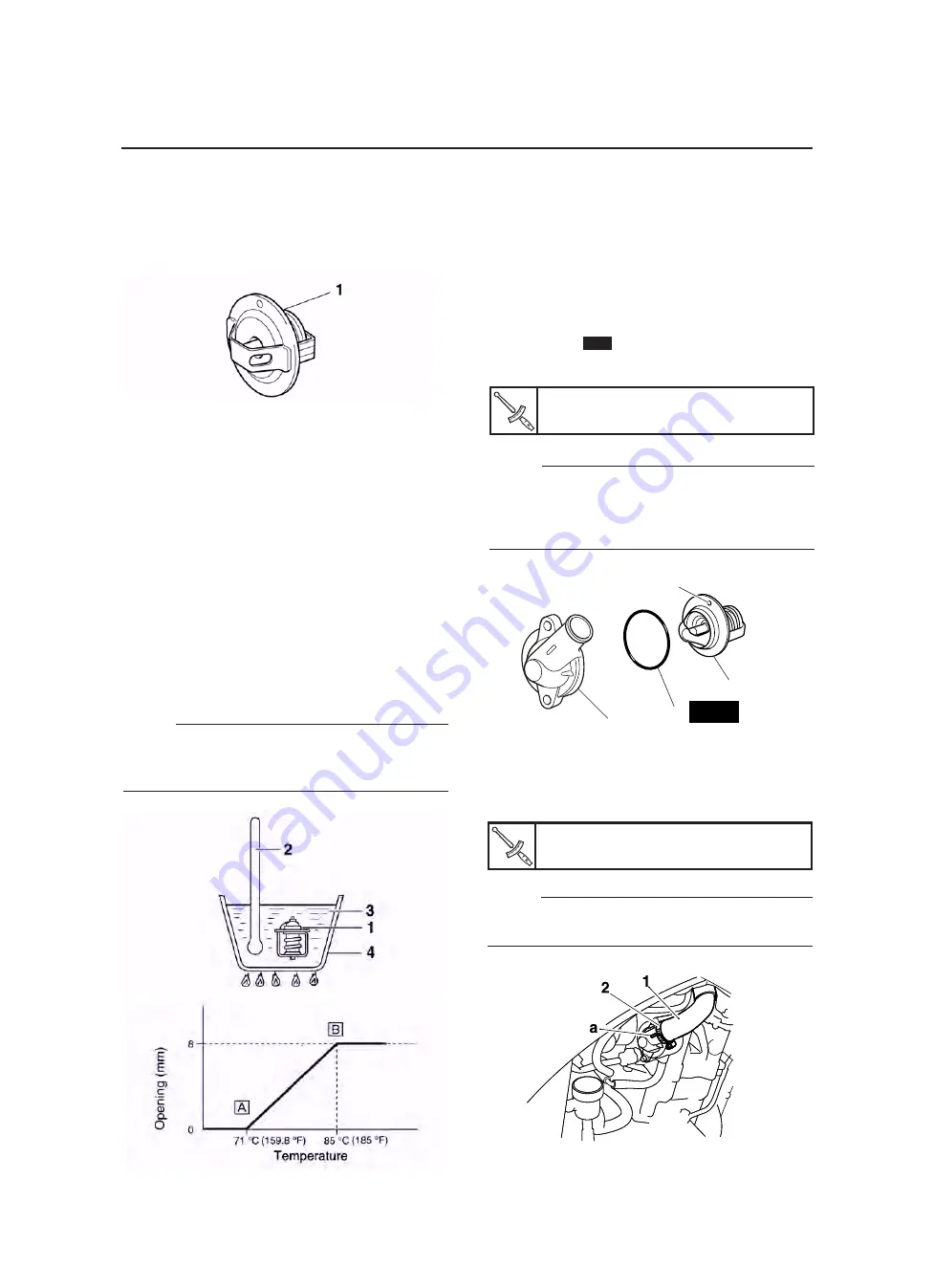
CHECKING THE THERMOSTAT
1. Check:
• Thermostat “1”
Does not open at 71-85 °C (159.8-185 °F)
→
Replace.
▼▼▼▼▼▼▼▼▼▼▼▼▼▼▼▼▼▼▼▼▼▼▼▼▼▼▼▼▼▼▼▼
a. Suspend the thermostat in a container filled
with water.
b. Slowly heat the water.
c. Place a thermometer in the water.
d. While stirring the water, observe the ther-
mostat and thermometer’s indicated tem-
perature.
1. Thermostat
2. Thermometer
3. Water
4. Container
å
Fully closed
∫
Fully open
NOTE:
If the accuracy of the thermostat is in doubt, re-
place it. A faulty thermostat could cause seri-
ous overheating or overcooling.
▼▼▼▼▼▼▼▼▼▼▼▼▼▼▼▼▼▼▼▼▼▼▼▼▼▼▼▼▼▼▼▼
2. Check:
• Thermostat cover
• Thermostat housing (cylinder head)
Cracks/damage
→
Replace.
EAS00466
INSTALLING THE THERMOSTAT
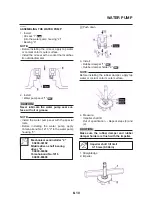
1. Install:
• Thermostat “1”
• O-ring “2”
• Thermostat cover “3”
New
Thermostat cover bolts
10 Nm (1.0 m·kg, 7.2 ft·lb)
NOTE:
• Install the thermostat with its breather hole “a”
facing up.
• Lubricate the O-ring with a thin coat of
lithium-soap-based grease.
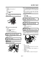
2. Install:
• Radiator inlet hose “1”
• Hose clamp “2”
New
3
2
1
a
NOTE:
Install the radiator inlet hose “1” so that it con-
tacts the projection on the thermostat cover “a”.
Hose clamp
Max 3 Nm (0.3 m·kg, 2.2 ft·lb)
Summary of Contents for MT-03
Page 7: ......
Page 9: ......
Page 25: ......
Page 53: ...2 28 COOLING SYSTEM DIAGRAMS 1 2 3 4 5 6 7 8 9 5 10 11 A B C ...
Page 56: ...2 31 LUBRICATION CHART Pressure feed Splashed scavenge ...
Page 57: ...2 32 LUBRICATION DIAGRAMS LUBRICATION DIAGRAMS A A 1 3 2 2 4 A A A A ...
Page 59: ...2 34 LUBRICATION DIAGRAMS A A A A 3 1 2 3 4 ...
Page 60: ...2 35 LUBRICATION DIAGRAMS 1 Oil delivery pipe 2 2 Oil delivery pipe 1 3 Oil filter 4 Oil pump ...
Page 61: ...2 36 LUBRICATION DIAGRAMS 1 7 2 3 4 5 6 A ...
Page 63: ...2 38 LUBRICATION DIAGRAMS 1 6 5 4 3 2 ...
Page 65: ...2 40 CABLE ROUTING CABLE ROUTING ...
Page 67: ...2 42 CABLE ROUTING ...
Page 69: ...2 44 CABLE ROUTING ...
Page 71: ...2 46 CABLE ROUTING ...
Page 73: ...2 48 CABLE ROUTING ...
Page 75: ...2 50 CABLE ROUTING ...
Page 77: ...2 52 CABLE ROUTING ...
Page 79: ...2 54 CABLE ROUTING ...
Page 81: ...2 56 CABLE ROUTING ...
Page 83: ...2 58 CABLE ROUTING ...
Page 85: ...2 60 CABLE ROUTING ...
Page 87: ......
Page 121: ......
Page 177: ...4 54 FRONT FORK WARNING Make sure the brake hoses are routed prop erly ...
Page 271: ......
Page 273: ......
Page 287: ......
Page 325: ......
Page 339: ...8 12 CHARGING SYSTEM 2 A C magneto 5 Rectifier regulator 7 Battery 8 Main fuse ...
Page 341: ...8 14 CHARGING SYSTEM ...
Page 355: ...8 28 COOLING SYSTEM ...
Page 365: ...8 38 IMMOBILIZER SYSTEM ...
Page 366: ...8 39 ELECTRICAL COMPONENTS EAS27970 ELECTRICAL COMPONENTS ...
Page 368: ...8 41 ELECTRICAL COMPONENTS ...
Page 370: ...8 43 ELECTRICAL COMPONENTS EAS27980 CHECKING THE SWITCHES ...
Page 389: ......
Page 391: ......
Page 397: ...COLOR CODE ...
Page 398: ......
Page 399: ...YAMAHA MOTOR ITALIA S P A ...
Page 400: ...MT 03 2006 WIRING DIAGRAM ...


