7-9
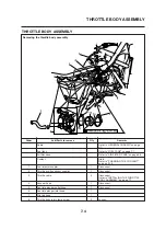
THROTTLE BODY ASSEMBLY
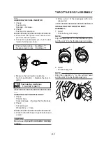
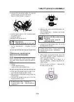
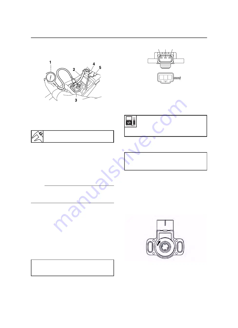
d. Connect the fuel pump coupler “4” and fuel
sender coupler “5” to the fuel pump.
Refer to “FUEL TANK” on page 7-1.
e. Set the main switch to “ON” and the engine
stop switch to “
I
”.
f. Start the engine.
g. Measure the fuel pressure.
Out of specification
→
Replace the fuel
pump.
Fuel pressure
324 kPa (3.24 kg/cm
2
, 46.1 psi)
▼▼▼▼▼▼▼▼▼▼▼▼▼▼▼▼▼▼▼▼▼▼▼▼▼▼▼▼▼▼▼▼
CHECKING AND ADJUSTING THE
THROTTLE POSITION SENSOR
Before adjusting the throttle position sensor,
the engine idling speed should be properly ad-
justed.
(removed from the throttle body)
▼▼▼▼▼▼▼▼▼▼▼▼▼▼▼▼▼▼▼▼▼▼▼▼▼▼▼▼▼▼▼▼
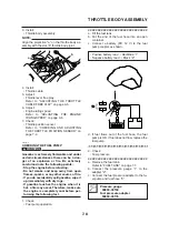
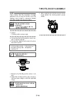
a. Disconnect the throttle position sensor cou-
pler from the throttle position sensor.
b. Remove the throttle position sensor from the
c. Connect the pocket tester (
d. Measure the maximum throttle position sen-
sor resistance.
Out of specification
→
Replace the throttle
position sensor.
L
Y
B
/
L
2
3
1
e. Connect the pocket tester (
Ω
x 1k) to the
throttle position sensor.
f. While slowly opening the throttle, check that
the throttle position sensor resistance is
within the specified range.
The resistance does not change or it
changes abruptly
→
Replace the throttle po-
sition sensor.
The slot is worn or broken
→
Replace the
throttle position sensor.
Maximum throttle position sensor
resistance
4.0-6.0 k
Ω
at 20 °C (68 °F)
(blue-black/blue)
• Positive tester probe
→
Yellow terminal “3”
• Negative tester probe
→
Black/Blue
terminal “2”
Summary of Contents for MT-03
Page 7: ......
Page 9: ......
Page 25: ......
Page 53: ...2 28 COOLING SYSTEM DIAGRAMS 1 2 3 4 5 6 7 8 9 5 10 11 A B C ...
Page 56: ...2 31 LUBRICATION CHART Pressure feed Splashed scavenge ...
Page 57: ...2 32 LUBRICATION DIAGRAMS LUBRICATION DIAGRAMS A A 1 3 2 2 4 A A A A ...
Page 59: ...2 34 LUBRICATION DIAGRAMS A A A A 3 1 2 3 4 ...
Page 60: ...2 35 LUBRICATION DIAGRAMS 1 Oil delivery pipe 2 2 Oil delivery pipe 1 3 Oil filter 4 Oil pump ...
Page 61: ...2 36 LUBRICATION DIAGRAMS 1 7 2 3 4 5 6 A ...
Page 63: ...2 38 LUBRICATION DIAGRAMS 1 6 5 4 3 2 ...
Page 65: ...2 40 CABLE ROUTING CABLE ROUTING ...
Page 67: ...2 42 CABLE ROUTING ...
Page 69: ...2 44 CABLE ROUTING ...
Page 71: ...2 46 CABLE ROUTING ...
Page 73: ...2 48 CABLE ROUTING ...
Page 75: ...2 50 CABLE ROUTING ...
Page 77: ...2 52 CABLE ROUTING ...
Page 79: ...2 54 CABLE ROUTING ...
Page 81: ...2 56 CABLE ROUTING ...
Page 83: ...2 58 CABLE ROUTING ...
Page 85: ...2 60 CABLE ROUTING ...
Page 87: ......
Page 121: ......
Page 177: ...4 54 FRONT FORK WARNING Make sure the brake hoses are routed prop erly ...
Page 271: ......
Page 273: ......
Page 287: ......
Page 325: ......
Page 339: ...8 12 CHARGING SYSTEM 2 A C magneto 5 Rectifier regulator 7 Battery 8 Main fuse ...
Page 341: ...8 14 CHARGING SYSTEM ...
Page 355: ...8 28 COOLING SYSTEM ...
Page 365: ...8 38 IMMOBILIZER SYSTEM ...
Page 366: ...8 39 ELECTRICAL COMPONENTS EAS27970 ELECTRICAL COMPONENTS ...
Page 368: ...8 41 ELECTRICAL COMPONENTS ...
Page 370: ...8 43 ELECTRICAL COMPONENTS EAS27980 CHECKING THE SWITCHES ...
Page 389: ......
Page 391: ......
Page 397: ...COLOR CODE ...
Page 398: ......
Page 399: ...YAMAHA MOTOR ITALIA S P A ...
Page 400: ...MT 03 2006 WIRING DIAGRAM ...

