7-37
FUEL INJECTION SYSTEM
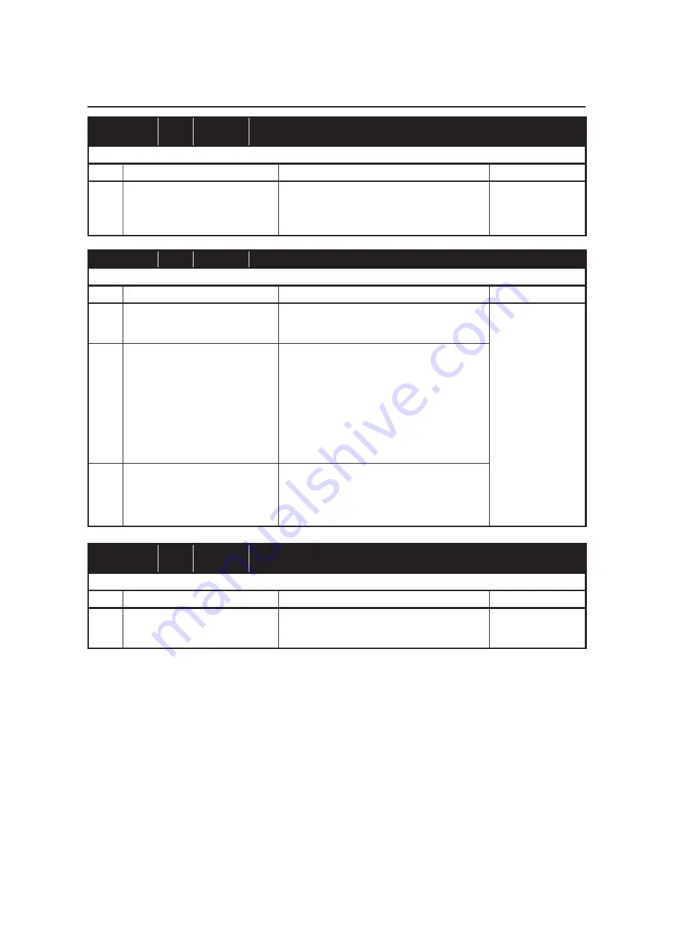
Fault code No.
44
Symptom
Error is detected while reading or writing on EEPROM
(CO adjustment value).
Used diagnostic code No. 60 (EEPROM improper cylinder indication)
Order
Item/components
Check or maintenance job
Restore method
1
Malfunction in ECU
Execute the diagnostic mode. (Code No. 60)
• Check the faulty cylinder.
• Readjust the CO of the displayed cylinder.
Replace the ECU if it is defective.
Reinstated by set-
ting the main switch
to “ON”.
Fault code No.
46
Symptom
Power supply to the FI system relay is not normal.
Used diagnostic code No. 09
Order
Item/components
Check or maintenance job
Restore method
1
Faulty battery
Replace or change the battery.
Refer to “CHECKING AND CHARGING THE
BATTERY”
Reinstated by start-
ing the engine and
operating it at idle.
2
Open or short circuit in the wire har-
ness.
Excute the diagnostic mode. (Code No. 09)
Repair or replace if there is an open or short cir-
cuit:
between battery and fuel injection system fuse
Red - Red
between the fuel injection system fuse and fuel
injection system relay
Brown - Brown
between the fuel injection system relay and ECU
Red/Blue - Red/Blue
3
Coupler connections ECU coupler
Check the coupler for any pins that may have
pulled out.
Check that the coupler is securely locked.
If necessary, repair the coupler or securely con-
nect it.
Fault code No.
50
Symptom
Faulty ECU memory. (When this malfunction is detected in the ECU, the fault
code number might not appear on the meter.)
Used diagnostic code No. – –
Order
Item/components
Check or maintenance job
Restore method
1
Malfunction in ECU
Replace the ECU.
Reinstated by set-
ting the main switch
to “ON”.
on page 3-29.
Summary of Contents for MT-03
Page 7: ......
Page 9: ......
Page 25: ......
Page 53: ...2 28 COOLING SYSTEM DIAGRAMS 1 2 3 4 5 6 7 8 9 5 10 11 A B C ...
Page 56: ...2 31 LUBRICATION CHART Pressure feed Splashed scavenge ...
Page 57: ...2 32 LUBRICATION DIAGRAMS LUBRICATION DIAGRAMS A A 1 3 2 2 4 A A A A ...
Page 59: ...2 34 LUBRICATION DIAGRAMS A A A A 3 1 2 3 4 ...
Page 60: ...2 35 LUBRICATION DIAGRAMS 1 Oil delivery pipe 2 2 Oil delivery pipe 1 3 Oil filter 4 Oil pump ...
Page 61: ...2 36 LUBRICATION DIAGRAMS 1 7 2 3 4 5 6 A ...
Page 63: ...2 38 LUBRICATION DIAGRAMS 1 6 5 4 3 2 ...
Page 65: ...2 40 CABLE ROUTING CABLE ROUTING ...
Page 67: ...2 42 CABLE ROUTING ...
Page 69: ...2 44 CABLE ROUTING ...
Page 71: ...2 46 CABLE ROUTING ...
Page 73: ...2 48 CABLE ROUTING ...
Page 75: ...2 50 CABLE ROUTING ...
Page 77: ...2 52 CABLE ROUTING ...
Page 79: ...2 54 CABLE ROUTING ...
Page 81: ...2 56 CABLE ROUTING ...
Page 83: ...2 58 CABLE ROUTING ...
Page 85: ...2 60 CABLE ROUTING ...
Page 87: ......
Page 121: ......
Page 177: ...4 54 FRONT FORK WARNING Make sure the brake hoses are routed prop erly ...
Page 271: ......
Page 273: ......
Page 287: ......
Page 325: ......
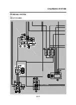
Page 339: ...8 12 CHARGING SYSTEM 2 A C magneto 5 Rectifier regulator 7 Battery 8 Main fuse ...
Page 341: ...8 14 CHARGING SYSTEM ...
Page 355: ...8 28 COOLING SYSTEM ...
Page 365: ...8 38 IMMOBILIZER SYSTEM ...
Page 366: ...8 39 ELECTRICAL COMPONENTS EAS27970 ELECTRICAL COMPONENTS ...
Page 368: ...8 41 ELECTRICAL COMPONENTS ...
Page 370: ...8 43 ELECTRICAL COMPONENTS EAS27980 CHECKING THE SWITCHES ...
Page 389: ......
Page 391: ......
Page 397: ...COLOR CODE ...
Page 398: ......
Page 399: ...YAMAHA MOTOR ITALIA S P A ...
Page 400: ...MT 03 2006 WIRING DIAGRAM ...


