background image

8-25

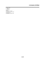
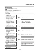
COOLING SYSTEM

EAS00807

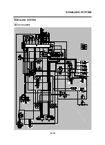
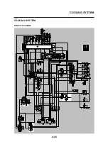
COOLING SYSTEM

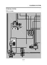
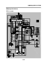
CIRCUIT DIAGRAM

17

28

29

30

31

32

33

34

35

36

A

50

49

48

47

46

A

2

9

14

12

42

41

YW

12V10W

TA

C

H

O

G

Ch

B1

BW

YW

BrL

BrL

BrR

BrR

B

L

L

R

7.5A

(BLACK)

L

B

(BLACK)

R

B

R

R

R

B

P

P

B

LR

B

LR

12V5W

Br

BrW

-

FUEL

Lg

WY

BL

BL
Y
L

(BLACK)

BL

GW

GW

B

LR

YG

B

LR

YG

B

RL

B

GW

YG

YG

L

L

L

Br

L

GY

RW

Or

Or

RB

RB

R

LW

BrW

BrW

RW

BY

Gy

Gy

PW

PW

L

L

W

ATER TEMP

HI BEAM

TURN

NEUTRAL

Ch

ILLUMINA

TION

GND

YW

GR

GR

WY

SPEED

+V

BACKUP

12V21/5W

HI BEAM

EL

FUEL

EG

YL

R
B

B

YL

R

R

YL

B

Dg

WY

EG

Ch

LR

LR

B

12V5W

B

B

BrW

BrW

GW

BL

GR

GR

W

W

BL

BL

BL

-
-

-

BL
YG
L

LB

10A

B

BL

BL
GR

(BLACK)

RG

RG

R

10A

W

W

LW

LW

RL

RL

B
B

(BLUE)

LG

B

(BLUE)

RW

G

Y

LW

BrW

RL

Ch

-

P

Lg

Br

Dg

Y

LB
BrW
RY

Ch

-

P
G

Br

OFF

ON

HORN

HIGH

LOW

DIMMER

L

PW

BL

(BLACK)

LW

T

ACHO

RW

GY

GY

Br

Br

R

MONIT

OR

RELA

Y

ST

AND

A/TEMP

W/TEMP

S/Vcc

SPEED

S/GND

TPS

Pb

EG ST

OP

INJ1

IG

C/GND

LAN

AIS

CRANK

VB

ST

AR

T

IG/GND

NT

HLR

FA

R

Or
RB

R

BrR

L

BW
Gy
W


YG
YL
LW

B

RL
YB
GY
LR
BL
Y

PW
BrW
GR
LB
BY

Lg

Y

YG

YG

B

RW

R

R

10A

B

Sb

Sb

BB2
BB3

BB1

BB4

Br

Br

RL

10A

FREE

PUSH

ST

AR

T

OFF

RUN

EG ST

OP

RW

LW

RB

B

R

LB

RB

B

RB

LB

LB

LY

LY

BY

BY

BB4

BB3

W

GL

GL

BB
B1

B2

B1

Y

B

LR

LR

B

B

OFF

ON

HAZARD

OFF

ON

P

ASS.

L

N

R

FLASHER

BB

BB

Y

Y

GND

+V

FL(L)

B
B

Br

FL(R)

G

B

LR

R

B

W

W

W

LR

RL

RL

RB

RB

RB

Sb

Sb

RW

BB1

BB2

BACK UP

LG

LG

IMOBI

RG

RL

LR

LR

B

BACK UP

IND.

IGN.

ALARM

CTIC

GND

B

B2

RG

YL

Lg

RW

B

BB

RG

YL

GL

RW

LY

BY

B
B

Br

P

OrR

BW

W

L

BL

BB

BB

YL

YL

B

BrW

BL

(BLACK)

BrR

BrR

RL

LW

YB

RY

RL

RL

BrL

BrL

LR

Lg

Lg

RW
BrR

(DARK BLUE)

R

Br

Br

20A

RW

YB

YB

RY

LW

LW

10A

Br

YG

Br

Br

B

B

B

W

W

BW

B

B

W

W

ON

OFF

P

MAIN

BrR

R

BrL

BrR

R

BrL

Gy

GW

W

W

W

LY

GW

W
W

W

R

R

B

B

B

RL

LB

RB

-

LW

Br

Lg

BY

Sb

LY
LG
RW
LR
LW

-

-

R

R

30A

R
R

LW

RW

Br

(BLACK)

B
B

(BLACK)

Y

12V60/55W

G

YB

B

12V10W

W

IMMOBI

LR


LR

B


YG

LR


B


GL

GR

Y

W

YW

Lg

G

Ch

RG

BW

WY

GW

RW

B

LR

YG

Ch

G

-

-

B

Dg

-

B

Ch

B

-

-

B

Ch

B

-

Dg

-

B

Ch

B

Ch

Dg

-

B

B

Dg

B

Dg

Dg

12V10W

12V10W

12V10W

B

B

12V10W

Ch

Ch

G

Ch

YG

LR

B

EXTN. WIRE HARNESS

MAIN HARNESS

BLACK

BLACK

BLACK

BLACK

GRA

Y

GRA

Y

GRA

Y

GRA

Y

GRA

Y

(

)

43

44

62

63

64

65

66

67

23

26

25

24

21

20

19

18

16

15

13

8

10

11

7

6

5

3

1

4

72

71

70

69

40

39

38

37

68

27

45

51

61

52

53

54

55

56

57

58

59

60

YG

YG

22

Summary of Contents for MT-03

Page 1: ...MT 03 SERVICE MANUAL 2006 5YK F8197 E0 cn LazAruS o Administrator ou MTOC email admin mt oc org uk c GB ...

Page 2: ...UAL 2006 by Yamaha Motor Italia S p A First edition February 2006 All rights reserved Any reproduction or unauthorized use without the written permission of Yamaha Motor Italia S p A is expressly prohibited Printed in Italy ...

Page 3: ...dels Modifications and sig nificant changes in specifications or procedures will be forwarded to all authorized Yamaha dealers and will appear in future editions of this manual where applicable NOTE Designs and specifications are subject to change without notice EAS00040 IMPORTANT MANUAL INFORMATION Particularly important information is distinguished in this manual by the following The Safety Aler...

Page 4: ...h page Sub section titles 2 appear in smaller print than the section title To help identify parts and clarify procedure steps there are exploded diagrams 3 at the start of each removal and disassembly section Numbers 4 are given in the order of the jobs in the exploded diagram A number indicates a dis assembly step Symbols 5 indicate parts to be lubricated or replaced Refer to SYMBOLS A job instru...

Page 5: ...e mounted 2 Filling fluid 3 Lubricant 4 Special tool 5 Tightening torque 6 Wear limit clearance 7 Engine speed 8 Electrical data 9 Engine oil 10 Gear oil 11 Molybdenum disulfide oil 12 Wheel bearing grease 13 Lithium soap based grease 14 Molybdenum disulfide grease 15 Apply locking agent LOCTITE 16 Replace the part with a new one New 1 2 3 4 5 7 8 6 9 11 10 12 14 13 15 16 ...

Page 6: ...GENERAL INFORMATION TABLE OF CONTENTS 1 SPECIFICATIONS 2 PERIODIC CHECKS AND ADJUSTMENTS 3 CHASSIS 4 ENGINE 5 COOLING SYSTEM 6 FUEL INJECTION SYSTEM 7 ELECTRICAL SYSTEM 8 TROUBLESHOOTING 9 ...

Page 7: ......

Page 8: ... THE FI SYSTEM 1 2 FI SYSTEM 1 3 INSTRUMENT FUNCTIONS 1 4 IMPORTANT INFORMATION 1 7 PREPARATION FOR REMOVAL AND DISASSEMBLY 1 7 REPLACEMENT PARTS 1 7 GASKETS OIL SEALS AND O RINGS 1 7 LOCK WASHERS PLATES AND COTTER PINS 1 7 BEARINGS AND OIL SEALS 1 8 CIRCLIPS 1 8 CHECKING THE CONNECTIONS 1 9 SPECIAL TOOLS 1 10 1 ...

Page 9: ......

Page 10: ...TIFICATION NUMBER The vehicle identification number 1 is stamped into the right side of the steering head pipe EAS00180 MODEL LABEL The model label 1 is affixed to the frame un der the passenger seat This information will be needed to order spare parts 1 1 ...

Page 11: ...tio in a more precise and finely tuned manner To accommodate this need this model has adopted an electroni cally controlled fuel injection FI system in place of a conventional carburetor system This system can achieve an optimum air fuel ratio required by the engine at all times by using a microprocessor that regulates the fuel injection volume according to the engine operating conditions detected...

Page 12: ...r the volume of fuel that is supplied The injection duration and the injection timing are controlled by the ECU Signals that are input from the throttle position sensor crankshaft position sensor intake air pressure sensor intake air temper ature sensor and coolant temperature sensor enable the ECU to determine the injection duration The injection timing is determined through the signal from the c...

Page 13: ...uel reserve tripmeter which shows the distance traveled since the fuel level warning light came on a clock a self diagnosis device an indicator lights brightness control mode To switch the speedometer and odometer trip meter displays between kilometers and miles push the SELECT and RESET buttons to gether and turn the key to ON When the dig its start flashing on the display push the SE LECT button...

Page 14: ...wing order F TRIP 6 ODO 6 TRIP 1 6 TRIP 2 6 F TRIP To reset a tripmeter select it by pushing the SE LECT button and then push the RESET button for at least four seconds If you do not reset the fuel reserve tripmeter manually it will reset itself automatically and the display will return to the pri or mode after refueling and traveling 5 km 3 mi 1 2 Clock mode 1 Clock 2 SELECT button 3 RESET button...

Page 15: ...the main switch and do not keep more than one immobilizer key on the same key ring Immobilizer system keys may cause signal in terference which may prevent the engine from starting 2 If the engine starts turn it off and try starting the engine with the standard keys 3 If one or both of the standard keys do not start the engine re register the standard keys If the multifunction display indicates an...

Page 16: ...correct installation of all parts 5 Keep all parts away from any source of fire EAS20200 REPLACEMENT PARTS Use only genuine Yamaha parts for all replace ments Use oil and grease recommended by Yamaha for all lubrication jobs Other brands may be similar in function and appearance but inferior in quality EAS20210 GASKETS OIL SEALS AND O RINGS 1 When overhauling the engine replace all gaskets seals a...

Page 17: ...rease Oil bearings liberally when installing if appropriate ECA13300 CAUTION Do not spin the bearing with compressed air because this will damage the bearing surfaces EAS20240 CIRCLIPS Before reassembly check all circlips carefully and replace damaged or distorted circlips Al ways replace piston pin clips after one use When installing a circlip 1 make sure the sharp edged corner 2 is positioned op...

Page 18: ...sconnect sev eral times 3 Check All connections Loose connection Connect properly NOTE If the pin 1 on the terminal is flattened bend it up 4 Connect Lead Coupler Connector NOTE Make sure all connections are tight 5 Check Continuity with the pocket tester Pocket tester 90890 03112 NOTE If there is no continuity clean the terminals When checking the wire harness perform steps 1 to 3 As a quick reme...

Page 19: ...bers or both may differ depending on the country When placing an order refer to the list provided below to avoid any mistakes Tool name Tool No Illustration Reference pages Pocket tester 90890 03112 Digital circuit tester 90890 03174 Fuel injection system tester 90890 03182 Timing light 90890 03141 Ignition checker 90890 06754 Compression gauge 90890 03081 Adaptor Compression gauge 90890 04082 5 5...

Page 20: ...890 03176 Radiator cap tester 90890 01325 Radiator cap tester adaptor 90890 01352 Radiator cap tester adapter 90890 01497 Radiator tester adapter 90890 01496 Thickness gauge 90890 03079 Valve spring compressor attachment 90890 01243 Valve spring compressor 90890 04019 7 8 7 8 6 2 6 3 6 2 6 2 6 3 6 2 6 3 3 4 5 21 5 26 ...

Page 21: ...083 Weight 90890 01084 Piston pin puller set 90890 01304 Valve guide remover ø 6 90890 04064 Valve guide installer ø 6 90890 04065 Valve guide reamer ø 6 90890 04066 Valve lapper 90890 04101 Flywheel puller 90890 01362 Sheave holder 90890 01701 5 16 5 18 5 28 5 22 5 22 5 22 5 22 5 54 5 54 5 56 ...

Page 22: ...staller pot 90890 01274 Crankshaft installer bolt 90890 01275 Adapter 90890 04130 Spacer crankshaft installer 90890 04144 Middle driven shaft bearing driver 90890 04058 Mechanical seal installer 90890 04132 Engine alignment tool 90890 11097 Steering nut wrench 90890 01403 Ring nut wrench 90890 01268 5 36 5 38 5 68 5 69 5 69 6 10 5 7 3 24 4 57 4 58 4 57 ...

Page 23: ...No Illustration Reference pages T handle 90890 01326 Damper rod holder 90890 01460 Fork seal driver weight 90890 01367 Fork seal driver attachment ø 43 90890 01374 Yamaha bond No 1215 90890 85505 4 49 4 51 4 51 4 52 5 56 5 63 5 65 6 10 ...

Page 24: ...ICATIONS 2 13 TIGHTENING TORQUES 2 16 GENERAL TIGHTENING TORQUE SPECIFICATIONS 2 16 ENGINE TIGHTENING TORQUES 2 17 CHASSIS TIGHTENING TORQUES 2 20 LUBRICATION POINTS AND LUBRICANT TYPES 2 23 ENGINE 2 23 CHASSIS 2 25 COOLING SYSTEM DIAGRAMS 2 26 LUBRICATION CHART 2 30 LUBRICATION DIAGRAMS 2 32 CABLE ROUTING 2 40 2 ...

Page 25: ......

Page 26: ...nsions Overall length 2070 mm 81 49 in Overall width 860 mm 33 85 in Overall height 1115 mm 43 89 in Seat height 805 mm 31 69 in Wheelbase 1420 mm 55 90 in Minimum ground clearance 200 mm 7 87 in Minimum turning radius 2225 mm 87 59 in Weight With oil and fuel 192 kg 423 lb Maximum load 186 kg 410 lb ...

Page 27: ...ine oil Lubrication system Dry sump Oil type SAE10W30 or SAE10W40 or SAE15W40 or SAE20W40 or SAE20W50 Recommended engine oil grade API service SE SF SG type or higher Engine oil quantity Total amount 3 40 L 2 99 Imp qt 3 60 US qt Without oil filter element replacement 3 00 L 2 64 Imp qt 3 17 US qt With oil filter replacement 3 10 L 2 72 Imp qt 3 28 US qt Oil filter Oil filter type Paper Oil pump O...

Page 28: ...Depth 23 0 mm 0 91 in Coolant reservoir Capacity 0 25 L 0 26 US qt 0 22 Imp qt From low to full level 0 15 L 0 16 US qt 0 13 Imp qt Water pump Water pump type Single suction centrifugal pump Reduction ratio 27 28 0 964 Maximum impeller shaft tilt 0 15 mm 0 006 in Spark plug Manufacturer Model NGK CR7E Spark plug gap 0 7 0 8 mm 0 028 0 031 in Cylinder head Volume 59 10 60 50 cm3 3 61 3 69 cu in Max...

Page 29: ...07 mm 1 4570 1 4609 in Limit 36 907 mm 1 4530 in Valve timing Intake open B T D C 25 Intake closed A B D C 55 Exhaust open B B D C 60 Exhaust closed A T D C 20 Overlap angle A 45 Maximum camshaft runout 0 030 mm 0 0012 in Timing chain Model number of links 98 x RH2010 126 Tensioning system Automatic Rocker arm rocker arm shaft Rocker arm inside diameter 12 000 12 018 mm 0 4724 0 4731 in Limit 12 0...

Page 30: ...ve seat width C intake 1 00 1 20 mm 0 0394 0 0472 in Limit 1 6 mm 0 06 in Valve seat width C exhaust 1 00 1 20 mm 0 0394 0 0472 in Limit 1 6 mm 0 06 in Valve margin thickness D intake 0 80 1 20 mm 0 0315 0 0472 in Valve margin thickness D exhaust 0 80 1 20 mm 0 0315 0 0472 in Valve stem diameter intake 5 975 5 990 mm 0 2352 0 2358 in Limit 5 945 mm 0 2341 in Valve stem diameter exhaust 5 960 5 975...

Page 31: ...8 mm 1 59 in Limit 38 36 mm 1 51 in Free length exhaust 40 38 mm 1 59 in Limit 38 36 mm 1 51 in Installed length valve closed intake 35 00 mm 1 38 in Installed length valve closed exhaust 35 00 mm 1 38 in Compressed spring force installed intake 171 00 197 00 N 38 44 44 29 lb 17 44 20 09 kg Compressed spring force installed exhaust 171 00 197 00 N 38 44 44 29 lb 17 44 20 09 kg Spring tilt intake 2...

Page 32: ...052 0 9055 in Limit 22 971 mm 0 9044 in Piston pin to piston pin bore clearance 0 004 0 024 mm 0 0002 0 0009 in Limit 0 074 mm 0 0029 in Ring Top ring Ring type Barrel Dimensions B x T 1 20 x 3 80 mm 0 047 x 0 150 in End gap installed 0 20 0 35 mm 0 0079 0 0138 in Limit 0 60 mm 0 0236 in Ring side clearance 0 030 0 080 mm 0 0012 0 0031 in Limit 0 13 mm 0 0051 in 2nd ring Ring type Taper Dimensions...

Page 33: ...Small end free play F 0 16 0 40 0 0063 0 0157 in Balancer Balancer drive method Gear Clutch Clutch type Wet multiple disc Clutch release method Outer pull rack and pinion pull Operation Left hand operation Clutch cable free play at the end of the clutch lever 10 0 15 0 mm 0 39 0 59 in Friction plates 1 inside dia 120 mm Thickness 2 90 3 10 mm 0 114 0 122 in Limit 2 80 mm 0 110 in Plate quantity 4 ...

Page 34: ... 0 909 5th gear 20 26 0 769 Maximum main axle runout 0 08 mm 0 0031 in Maximum drive axle runout 0 08 mm 0 0031 in Shifting mechanism Shift mechanism type Shift drum and guide bar Shift fork thickness 5 76 5 89 mm 0 2267 0 23188 in Decompression device Device type Auto decompression Air filter Air filter type Oil coated paper element Fuel pump Pump type Electrical Model manufacturer 5VK DENSO Cons...

Page 35: ...Maximum lateral wheel runout 0 5 mm 0 02 in Wheel axle bending limit 0 25 mm 0 01 in Front tire Tire type Tubeless Size 120 70 ZR17M C 58W 120 70 R17M C 58H Manufacturer model DUNLOP D270F PIRELLI SCORPION SYNC Minimum tire tread depth 1 6 mm 0 063 in Rear tire Tire type Tubeless Size 160 60 ZR17M C 69W 160 60 R17M C 69H Manufacturer model DUNLOP D270 PIRELLI SCORPION SYNC Minimum tire tread depth...

Page 36: ... in Caliper cylinder inside diameter 30 16 mm x 2 1 18 in x 2 and 25 40 mm x 2 1 10 in x 2 Rear brake Brake type Single disc brake Operation Right foot operation Brake pedal position below the top of the rider footrest 14 5 mm 0 57 in Recommended fluid DOT 4 Brake discs Diameter x thickness 245 x 5 0 mm 9 65 x 0 20 in Minimum thickness 4 5 mm 0 18 in Maximum deflection 0 15 mm 0 006 in Pad thickne...

Page 37: ...0 mm 3 74 in Inner tube outer diameter 43 0 mm 1 69 in Inner tube bending limit 0 2 mm 0 0079 in Rear suspension Suspension type Swingarm Rear shock absorber assembly type Coil spring gas oil damper Rear shock absorber assembly travel 51 0 mm 2 00 in Spring Free length 180 0 mm 7 08 in Limit 165 5 mm 6 51 in Installed length 170 0 mm 6 69 in Spring rate K1 120 00 N mm 685 20 lb in 12 24 kg mm Spri...

Page 38: ... Primary coil resistance 3 4 4 6 Ω at 20 C 68 F Secondary coil resistance 10 4 15 6 kΩ at 20 C 68 F Spark plug cap Material Rubber Resistance 10 0 kΩ at 20 C 68 F Charging system System type A C magneto Model manufacturer LMX51 DENSO Nominal output 14 0 V 20 8 A at 5000 r min Stator coil resistance color 0 224 0 336 Ω at 20 C 68 F white white Rectifier regulator Regulator type Semiconductor short ...

Page 39: ...stem type Constant mesh Starter motor Model manufacturer SM 13 MITSUBA Power output 0 80 kW Armature coil resistance 0 025 0 035 Ω at 20 C 68 F Brushes Overall length 12 5 mm 0 49 in Limit 5 00 mm 0 20 in Spring force 7 65 10 01 N 27 51 36 01 oz 780 1 021 gf Commutator diameter 28 0 mm 1 10 in Limit 27 mm 1 06 in Mica undercut 0 70 mm 0 028 in Starter relay Model manufacturer MS5F 421 JIDECO Amper...

Page 40: ...1 DENSO Output voltage 3 4 3 8 V Intake air temperature sensor Model manufacturer 5VU1 DENSO Resistance 2 21 2 69 kΩ at 20 C 68 F 0 290 0 354 kΩ at 80 C 176 F Coolant temperature sensor Model manufacturer 5PS1 DENSO Resistance 2 28 2 63 kΩ at 20 C 68 F 0 305 0 331 kΩ at 80 C 176 F 0 138 0 145 kΩ at 110 C 230 F Fuses amperage Main fuse 30 A Signaling system fuse 10 A Headlight fuse 20 A Ignition fu...

Page 41: ... avoid warpage tighten multi fastener assemblies in a criss cross pattern and progressive stages until the specified tightening torque is reached Unless otherwise specified tightening torque specifi cations require clean dry threads Components should be at room temperature A Distance between flats B Outside thread diameter A B General tightening nut bolt torques Nm m kg ft lb 10 mm 6 mm 6 0 6 4 3 ...

Page 42: ...g 7 2 ft lb Tappet cover exhaust side M6 4 10 Nm 1 0 m kg 7 2 ft lb Tappet cover intake side M6 4 10 Nm 1 0 m kg 7 2 ft lb Camshaft sprocket cover M6 2 10 Nm 1 0 m kg 7 2 ft lb Camshaft sprocket M7 2 20 Nm 2 0 m kg 14 ft lb Camshaft retainer M6 2 10 Nm 1 0 m kg 7 2 ft lb Valve adjusting screw M6 4 14 Nm 1 4 m kg 10 ft lb Use a lock Balancer driven gear M18 1 70 Nm 7 0 m kg 50 ft lb washer Use the ...

Page 43: ...Nm 1 8 m kg 13 ft lb Oil delivery hose 1 M6 1 10 Nm 1 0 m kg 7 2 ft lb Oil delivery hose 2 M6 2 10 Nm 1 0 m kg 7 2 ft lb Sealant Throttle body joint clamp screw M4 2 6 Nm 0 6 m kg 4 3 ft lb Air filter case joint clamp screw M5 1 4 Nm 0 4 m kg 2 9 ft lb Air filter case M6 4 10 Nm 1 0 m kg 7 2 ft lb Exhaust pipe joint M8 2 18 Nm 1 8 m kg 13 ft lb Exhaust pipe and frame M8 1 25 Nm 2 5 m kg 18 ft lb E...

Page 44: ...6 3 10 Nm 1 0 m kg 7 2 ft lb Crankshaft position sensor M5 2 7 Nm 0 7 m kg 5 1 ft lb Starter motor and crankcase M6 2 10 Nm 1 0 m kg 7 2 ft lb Starter motor lead M6 1 5 Nm 0 5 m kg 3 6 ft lb Brush holder and starter motor yoke M6 1 11 Nm 1 1 m kg 8 ft lb Starter motor assembly M5 2 5 Nm 0 5 m kg 3 6 ft lb Drive axle oil seal retainer M6 2 10 Nm 1 0 m kg 7 2 ft lb Sealant Use the Drive sprocket M18...

Page 45: ...Oil tank assembly L H M8 1 25 Nm 2 5 m kg 18 ft lb and frame Oil tank assembly R H M6 2 11 Nm 1 1 m kg 8 ft lb and frame Rear arm and side suspension Pivot shaft and frame M16 1 92 Nm 9 2 m kg 66 ft lb Side suspension and rear arm M10 1 50 Nm 5 0 m kg 36 ft lb Side suspension and frame M12 1 155 Nm 15 5 m kg 112 ft lb Rear fender cover and rear arm M6 4 9 Nm 0 9 m kg 6 5 ft lb Seal guard and rear ...

Page 46: ... M6 4 4 Nm 0 4 m kg 2 9 ft lb Fuel tank and knee pad inside M5 2 1 3 Nm 0 13 m kg 0 94 ft lb Max Fuel tank cap and fuel tank M5 4 6 Nm 0 6 m kg 4 3 ft lb Pipe breather joint and fuel tank M6 2 2 Nm 0 2 m kg 1 4 ft lb 572 or 222 Scoop air and stay scoop air M6 4 7 Nm 0 7 m kg 5 1 ft lb Driver seat and frame M6 2 7 Nm 0 7 m kg 5 1 ft lb Regulator and frame M6 2 10 Nm 1 0 m kg 7 2 ft lb Horn and fram...

Page 47: ...2 ft lb Union bolt tightening M10 1 30 Nm 3 0 m kg 22 ft lb rear caliper Idrostop and rear master cylinder M10 1 24 Nm 2 4 m kg 17 5 ft lb Bleeder tightening rear M10 1 14 Nm 1 4 m kg 10 ft lb Drive chain adjusting locknut M8 2 16 Nm 1 6 m kg 11 ft lb Footrest and pedal Side stand and frame M10 2 63 Nm 6 3 m kg 46 ft lb Side stand mounting bolt and nut M10 1 46 Nm 4 6 m kg 33 ft lb Side stand swit...

Page 48: ...and exhaust Valve stem ends intake and exhaust Rocker arm shaft Camshaft lobes Decompressor lever pin Decompressor lever spring Water pump impeller shaft Oil pump rotors inner and outer Oil pump shaft Torque limiter Starter clutch idle gear thrust surface Starter clutch idle gear inner surface Starter clutch gear inner and outer Starter clutch assembly Primary drive gear tightening nut Primary dri...

Page 49: ...ion point Lubricant Shift shaft spacer Crankcase mating surface Yamaha bond No 1215 A C magnet lead grommet A C magneto cover Yamaha bond No 1215 Oil seal holder tightening bolt Yamaha bond No 1215 Oil delivery hose 2 tightening bolt Yamaha bond No 1215 ...

Page 50: ...ing bolt outer surface Rear arm and rear shock absorber oil seal lips Brake pedal outer surface Rear brake master cylinder pin outer surface Steering head pipe bearings upper and lower Steering head pipe bearing races upper and lower Tube guide throttle grip inner surface Clutch lever pivot bolt outer surface Sidestand sliding surface and collar outer surface Footrest pivoting point Footrest sprin...

Page 51: ...2 26 COOLING SYSTEM DIAGRAMS EAS00033 COOLING SYSTEM DIAGRAMS 5VK 5VK00 A 4 A B 4 3 2 1 2 3 1 A A A ...

Page 52: ...2 27 COOLING SYSTEM DIAGRAMS 1 Water jacket joint 2 Water pump outlet hose 3 Water pump outlet pipe 4 Water pump A From the radiator B To the cylinder ...

Page 53: ...2 28 COOLING SYSTEM DIAGRAMS 1 2 3 4 5 6 7 8 9 5 10 11 A B C ...

Page 54: ...lant reservoir hose 3 Coolant reservoir breather hose 4 Radiator cap 5 Radiator 6 Coolant reservoir cap 7 Coolant reservoir 8 Radiator outlet hose 9 Water pump 10 Radiator fan 11 Radiator inlet hose A From the fast idle plunger B To the cylinder C From the thermostat ...

Page 55: ...2 30 LUBRICATION CHART LUBRICATION CHART Oil strainer Oil pump rotor 2 Check ball Oil filter Cylinder head Drive axle Crankshaft Camshaft Oil tank Main axle Oil pan Oil pump rotor 1 Connecting rod ...

Page 56: ...2 31 LUBRICATION CHART Pressure feed Splashed scavenge ...

Page 57: ...2 32 LUBRICATION DIAGRAMS LUBRICATION DIAGRAMS A A 1 3 2 2 4 A A A A ...

Page 58: ...2 33 LUBRICATION DIAGRAMS 1 Oil delivery hose 2 2 Oil strainer 3 Oil delivery hose 1 4 Oil tank ...

Page 59: ...2 34 LUBRICATION DIAGRAMS A A A A 3 1 2 3 4 ...

Page 60: ...2 35 LUBRICATION DIAGRAMS 1 Oil delivery pipe 2 2 Oil delivery pipe 1 3 Oil filter 4 Oil pump ...

Page 61: ...2 36 LUBRICATION DIAGRAMS 1 7 2 3 4 5 6 A ...

Page 62: ...2 37 LUBRICATION DIAGRAMS 1 Oil delivery hose 2 2 Oil delivery pipe 2 3 Oil filter 4 Oil pump rotor 1 5 Oil pump rotor 2 6 Main axle 7 Oil delivery pipe 3 A To oil tank ...

Page 63: ...2 38 LUBRICATION DIAGRAMS 1 6 5 4 3 2 ...

Page 64: ...2 39 LUBRICATION DIAGRAMS 1 Camshaft 2 Oil delivery pipe 1 3 Oil filter 4 Main axle 5 Drive axle 6 Crankshaft ...

Page 65: ...2 40 CABLE ROUTING CABLE ROUTING ...

Page 66: ...witch lead A Fasten the right handlebar switch lead with a plas tic band Face the end of the plastic band forward B Fasten the right handlebar switch lead and front brake light switch lead with a plastic band Face the end of the plastic band forward C Fasten the left handlebar switch lead and clutch switch lead with a plastic band Face the end of the plastic band forward D Fasten the clutch cable ...

Page 67: ...2 42 CABLE ROUTING ...

Page 68: ...Piece connecting and plastic band 5 Clutch cable 6 Clutch switch lead 7 Left handlebar switch lead 8 Front turn signal light coupler left 9 Auxiliary light coupler 10 Front brake hose holder 11 Headlight coupler 12 Front turn signal light coupler right 13 Front brake hose 14 Throttle cables ...

Page 69: ...2 44 CABLE ROUTING ...

Page 70: ...hose 3 Front fork under bracket 4 Front brake caliper left 5 Front brake caliper right 6 Brake caliper projection 7 Front mud guard A When installing the brake hose onto the brake caliper make sure that the brake pipe touches the projection on the brake caliper ...

Page 71: ...2 46 CABLE ROUTING ...

Page 72: ... Plastic band 9 Intake air temperature sensor lead 10 Intake air pressure sensor 11 Throttle position sensor lead 12 Fuel pump couplers 13 Air induction system lead 14 Battery 15 Battery cover 16 Negative battery lead 17 Main switch couplers 18 Immobilizer unit coupler A Fasten the wire harness negative battery lead and rear brake light switch lead to the frame with a plas tic band ...

Page 73: ...2 48 CABLE ROUTING ...

Page 74: ...tic band 2 Clutch cable 3 Starter motor 4 Negative battery lead 5 Starter negative lead 6 Rear brake pedal 7 Rear brake light switch 8 Rear brake master cylinder 9 Rear brake hose 10 Rear brake hose holder 11 Rear brake caliper ...

Page 75: ...2 50 CABLE ROUTING ...

Page 76: ...lead 3 Battery 4 Battery cover 5 Relay unit 6 Starter relay 7 Speed sensor lead 8 Intake air pressure sensor 9 Positive starter lead 10 Horn lead 11 Throttle cables 12 Reserve fuse 13 Main fuse 14 Left handlebar switch lead 15 Right handlebar switch lead ...

Page 77: ...2 52 CABLE ROUTING ...

Page 78: ...magneto lead 6 Speed sensor 7 Plastic band 8 Rubber protection 9 Rectifier regulator 10 Sidestand switch lead 11 Neutral switch lead 12 Starter motor 13 Hose holder 14 Main wire harness 15 Speed sensor lead 16 Wire holder 17 Negative battery lead 18 Negative coupler 19 Fuel tank breather overflow hoses ...

Page 79: ...2 54 CABLE ROUTING ...

Page 80: ...magneto lead 6 Speed sensor 7 Plastic band 8 Rubber protection 9 Rectifier regulator 10 Sidestand switch lead 11 Neutral switch lead 12 Starter motor 13 Hose holder 14 Main wire harness 15 Speed sensor lead 16 Wire holder 17 Negative battery lead 18 Negative coupler 19 Fuel tank breather overflow hoses ...

Page 81: ...2 56 CABLE ROUTING ...

Page 82: ...2 57 CABLE ROUTING 1 Battery cover 2 Plastic band 3 Plastic locking tie 4 Wire harness 5 Speed sensor coupler 6 ECU 7 Fuel pump couplers 8 Fuel injector lead ...

Page 83: ...2 58 CABLE ROUTING ...

Page 84: ...Turn signal hazard relay 2 Headlight relay 3 Radiator fan motor relay 4 Fuel injection diagnostic tool coupler 5 Anti theft alarm coupler 6 Fuse box 7 Plastic band 8 ECU 9 Lean angle cut off switch 10 Extension wire harness ...

Page 85: ...2 60 CABLE ROUTING ...

Page 86: ...ING 1 Tail brake light socket 2 Rear turn signal light coupler left 3 License plate light coupler 4 Rear turn signal light coupler right 5 Tail brake light coupler 6 Plastic band 7 Extension wire harness A Bottom view ...

Page 87: ......

Page 88: ...EATHER HOSES 3 13 CHECKING THE EXHAUST SYSTEM 3 14 CHECKING THE COOLANT LEVEL 3 14 CHECKING THE COOLING SYSTEM 3 15 CHANGING THE COOLANT 3 16 CHASSIS 3 18 ADJUSTING THE FRONT BRAKE 3 18 ADJUSTING THE REAR BRAKE PEDAL 3 18 CHECKING THE BRAKE FLUID LEVEL 3 19 CHECKING THE FRONT AND REAR BRAKE PADS AND BRAKE PAD PINS 3 20 CHECKING THE FRONT AND REAR BRAKE HOSES 3 20 BLEEDING THE HYDRAULIC BRAKE SYSTE...

Page 89: ... 29 CHECKING THE FUSES 3 29 REPLACING THE HEADLIGHT BULB 3 29 REPLACING AN AUXILIARY LIGHT BULB 3 29 REPLACING THE TAIL BRAKE LIGHT BULB 3 30 REPLACING A TURN SIGNAL LIGHT BULB 3 30 REPLACING THE LICENSE PLATE LIGHT BULB 3 31 ADJUSTING THE HEADLIGHT BEAM 3 31 ...

Page 90: ...learance See page 3 3 Adjust 4 Air filter element Replace See page 3 12 5 Clutch Check operation See page 3 11 Adjust Front brake Check operation fluid level and vehicle for fluid 6 See page 3 19 3 20 leakage Replace brake pads Whenever worn to the limit Rear brake Check operation fluid level and vehicle for fluid 7 See page 3 19 3 20 leakage Replace brake pads Whenever worn to the limit 8 Brake h...

Page 91: ...Every 3 years 25 Front and rear Check operation brake switches Moving parts and 26 cables Lubricate See page 3 28 Throttle grip Check operation and free play 27 housing and cable Adjust the throttle cable free play if necessary See page 3 5 Lubricate the throttle grip housing and cable Air induction Check the air cut off valve reed valve and hose 28 system for damage Check fuel hoses for cracks or...

Page 92: ...ter to air cut off valve hose Refer to AIR INDUCTION SYSTEM on page 7 11 2 Remove Intake tappet cover Exhaust tappet cover 1 Camshaft sprocket cover 2 3 Disconnect Spark plug cap 1 4 Remove Spark plug 2 2 1 5 Remove Timing mark accessing screw 1 Crankshaft end accessing screw 2 6 Valve clearance Out of specification Adjust 2 1 2 1 Valve clearance cold Intake valve 0 09 0 13 mm 0 0035 0 0051 in Exh...

Page 93: ... or b until the specified valve clearance is obtained Direction a Valve clearance is increased Direction b Valve clearance is decreased d Hold the adjusting screw to prevent it from moving and tighten the locknut to the speci fied torque a b e Measure the valve clearance again f If the valve clearance is still out of specifica tion repeat all of the valve clearance adjust ment steps until the spec...

Page 94: ...inutes 2 Check Engine idling speed Out of specification Adjust Engine idling speed 1300 1500 r min Direction a Engine idling speed is increased Direction b Engine idling speed is decreased 3 Adjust Engine idling speed a Turn the throttle stop screw 1 in direction a or b until the specified engine idling speed is obtained 1 a b 4 Adjust Throttle cable free play Refer to ADJUSTING THE THROTTLE CA BL...

Page 95: ...WARNING After adjusting the throttle cable free play start the engine and turn the handlebars to the right and to the left to ensure that this does not cause the engine idling speed to change EAS00060 CHECKING THE SPARK PLUG 1 Disconnect Spark plug cap 2 Remove Spark plug CAUTION Before removing the spark plug blow away any dirt accumulated in the spark plug well with compressed air to prevent it ...

Page 96: ... wiring connections of the entire ignition sys tem Make sure all connections are tight and free of corrosion a Start the engine warm it up for several min utes and then let it run at the specified en gine idling speed b Check that the stationary pointer a is with in the firing range b on the A C magneto rotor Incorrect firing range Check the ignition system 1 Remove Timing mark accessing screw 1 2...

Page 97: ... cm2 85 3 psi Standard 650 kPa 6 5 kg cm2 92 4 psi Maximum 700 kPa 7 0 kg cm2 99 6 psi a Set the main switch to ON and the engine stop switch to I b With the throttle wide open crank the engine until the reading on the compression gauge stabilizes WARNING To prevent sparking ground the spark plug lead before cranking the engine c If the compression pressure is above the maximum specification check...

Page 98: ... the frame 4 Check Engine oil level The engine oil level should be between the minimum level mark a and maximum level mark b Below the minimum level mark Add the recommended engine oil to the proper level 1 b a ECA10010 CAUTION Do not operate the vehicle until you know that the engine oil level is sufficient EWA10360 WARNING Never remove the engine oil tank cap after high speed operation otherwise...

Page 99: ...il completely from the crankcase and the oil tank 6 If the oil filter element is also to be replaced perform the following procedure 1 2 1 a Remove the oil filter element cover 1 and oil filter element 2 b Check the O rings 3 and replace them if they are cracked or damaged c Install the new oil filter element and the oil fil ter element cover 2 3 1 7 Check Engine oil drain bolt gasket Damage Repla...

Page 100: ...il en gine oil starts to seep from the bleed bolt If no engine oil comes out after one minute turn the engine off so that it will not seize 1 c Check the engine oil passages the oil filter element and the oil pump for damage or leakage Refer to OIL PUMP on page 5 41 d Start the engine after correcting the prob lem s and check the engine oil pressure again e Tighten the bleed bolt to the specified ...

Page 101: ... hose 1 for accumulated dirt water or oil If dirt water or oil is visible remove the hose clean it and then install it in its original position Remove the plug 3 drain any dirt water or oil and then in stall it in its original position If dust and or wa ter collects in these hoses clean the air filter element and air filter case 1 1 Remove Air filter case cover 1 2 Remove Air filter element 1 3 Ch...

Page 102: ...all Fuel tank Refer to FUEL TANK on page 7 1 Seats Refer to GENERAL CHASSIS on page 4 1 CHECKING THE FUEL TANK BREATHER OVERFLOW HOSES 1 Check Fuel tank breather overflow hoses 1 Loose connection Connect properly Cracks damage Replace CAUTION Make sure that the end of the fuel tank breather overflow hoses is not blocked and clean it if necessary Make sure that the end of the fuel tank breather ove...

Page 103: ... kg 13 ft lb Exhaust pipe and frame bolt 6 25 Nm 2 5 m kg 18 ft lb Exhaust pipe and muffler bolt 7 18 Nm 1 8 m kg 13 ft lb Muffler stay and muffler bolt 8 22 Nm 2 2 m kg 16 ft lb Muffler stay and frame bolt 9 22 Nm 2 2 m kg 16 ft lb EAS00102 CHECKING THE COOLANT LEVEL 1 Stand the motorcycle on a level surface NOTE Place the motorcycle on a suitable stand Make sure the motorcycle is upright 2 Check...

Page 104: ... min utes and then turn it off 4 Check Coolant level NOTE Before checking the coolant level wait a few minutes until it settles EAS00104 CHECKING THE COOLING SYSTEM 1 Remove Seats Refer to GENERAL CHASSIS on page 4 1 Fuel tank Refer to FUEL TANK on page 7 1 2 Check Radiator 1 Radiator outlet hose 2 Radiator inlet hose 3 Water pump assembly Water pump outlet pipe 4 Water pump outlet hose 5 Cracks d...

Page 105: ...wise toward the detent to allow any residual pressure to escape When the hissing sound has stopped press down on the radiator cap and turn it counterclockwise to remove 3 Remove Coolant reservoir cap 1 Coolant reservoir 2 4 Drain Coolant from the coolant reservoir 5 Install Coolant reservoir 1 2 Coolant reservoir bolt 5 Nm 0 5 m kg 3 6 ft lb 7 Drain Coolant from the engine and radiator 8 Check Cop...

Page 106: ... immediate medical attention CAUTION Adding water instead of coolant lowers the antifreeze content of the coolant If water is used instead of coolant check and if necessary correct the antifreeze concentration of the coolant Use only distilled water However if dis tilled water is not available soft water may be used If coolant comes into contact with painted surfaces immediately wash them with wat...

Page 107: ...ft or spongy feeling in the brake lever can indicate the presence of air in the brake system Before the vehicle is operat ed the air must be removed by bleeding the brake system Air in the brake system will considerably reduce braking perform ance and could result in loss of control and possibly an accident Therefore check the brake system and bleed if necessary 2 Adjust Brake pedal position c b 2...

Page 108: ...l Below the minimum level mark a Add the recommended brake fluid to the proper level Recommended brake fluid DOT 4 A Front brake B Rear brake A a WARNING Use only the designated brake fluid Other brake fluids may cause the piston seals to deteriorate causing leakage and poor brake performance Refill with the same type of brake fluid that is already in the system Mixing brake fluids may result in a...

Page 109: ...ached Replace the brake pads as a set Refer to REPLACING THE REAR BRAKE PADS on page 4 35 Rear brake pad wear limit 1 0 mm 0 04 in 4 Check Brake pad pins Damage wear Replace EAS00131 CHECKING THE FRONT AND REAR BRAKE HOSES The following procedure applies to all of the brake hoses and brake hose clamps 1 Check Front brake hoses 1 Rear brake hoses 2 Cracks damage wear Replace 2 Check Brake hose clam...

Page 110: ...recommended brake fluid b Install the diaphragm brake master cylinder reservoir or brake fluid reservoir c Connect a clear plastic hose 1 tightly to the bleed screw A Front brakes B Rear brake A k Fill the brake fluid reservoir to the proper level with the recommended brake fluid Refer to CHECKING THE BRAKE FLUID LEVEL on page 3 19 WARNING After bleeding the hydraulic brake system check the brake ...

Page 111: ...parts and one that is too loose can skip and damage the swingarm or cause an accident Therefore keep the drive chain slack within the spec ified limits ADJUSTING THE SHIFT PEDAL 1 Check Shift pedal position distance a from the top of the rider footrest to the top of the shift pedal Out of specification Adjust Shift pedal position from the top of the rider footrest to the top of the shift pedal 34 ...

Page 112: ...to clean the drive chain Wipe the drive chain dry and thoroughly lubricate it with engine oil or chain lubricant that is suitable for O ring chains Do not use any other lubricants on the drive chain since they may contain sol vents that could damage the O rings EAS00146 CHECKING AND ADJUSTING THE STEERING HEAD 1 Stand the motorcycle on a level surface WARNING Securely support the motorcycle so tha...

Page 113: ...all Upper bracket Washer Steering stem 8 Tighten Upper bracket pinch bolts 9 Install Handlebar Upper handlebar holders Steering stem nut 110 Nm 11 0 m kg 79 ft lb Upper bracket pinch bolt 23 Nm 2 3 m kg 17 ft lb Upper handlebar holder bolt 23 Nm 2 3 m kg 17 ft lb b Loosen the lower ring nut 4 and then tight en it to the specified torque with a steering nut wrench 5 NOTE Set the torque wrench at a ...

Page 114: ...vement Repair Refer to FRONT FORK on page 4 46 1 Adjust Spring preload NOTE Adjust the spring preload with the special wrench and extension bar included in the own er s tool kit a Loosen the locknut 2 b Turn the adjusting ring 1 in direction a or b 1 2 a b Direction a Spring preload is increased suspension is harder Direction b Spring preload is decreased suspension is softer Adjusting positions S...

Page 115: ...kgf cm2 30 psi 33 psi Total weight of rider passenger cargo and acces sories EAS00166 CHECKING THE TIRES The following procedure applies to both of the tires 1 Check Tire pressure Out of specification Regulate WARNING The tire pressure should only be checked and regulated when the tire temperature equals the ambient air temperature The tire pressure and the suspension must be adjusted according to...

Page 116: ...s should always be by the same manufacturer and of the same design No guarantee concerning handling character istics can be given if a tire combination other than one approved by Yamaha is used on this motorcycle Front tire Tire type Tubeless Size 120 70 ZR17M C 58W 120 70 R17M C 58H Manufacturer Model DUNLOP D270F PIRELLI SCORPION SYNC Rear tire Tire type Tubeless Size 160 60 ZR17M C 69W 160 60 R...

Page 117: ...side suspension must be lubricated at the intervals specified in the periodic maintenance and lubrication chart Recommended lubricant Lithium soap based grease Recommended lubricant Swingarm pivots Bearing grease Other pivoting points Lithium soap based grease EWA13260 WARNING Never attempt to make any repairs to the wheel NOTE After a tire or wheel has been changed or re placed always balance the...

Page 118: ...bulb 2 EWA13320 WARNING Since the headlight bulb gets extremely hot keep flammable products and your hands away from the bulb until it has cooled down 1 2 e Install Headlight bulb Secure the new headlight bulb with the headlight bulb holder ECA10650 CAUTION Take care not to damage the following parts Headlight bulb Do not touch the glass part of the head light bulb to keep it free from oil other w...

Page 119: ...light bulb into the socket by pushing it in and then turning it clockwise until it stops Tail brake light socket together with the bulb by turning it clockwise Tail brake light bulb cover Tail brake light bulb cover bolts d Tighten Tail brake light bulb cover bolts New 1 2 Tail brake light bulb cover bolt 10 Nm 1 0 m kg 7 2 ft lb REPLACING A TURN SIGNAL LIGHT BULB 1 Replace Turn signal light bulb ...

Page 120: ...ll too hard b Install License plate light bulb into the socket by pushing it in License plate light bulb socket by pushing it in Reinforcement plate Reinforcement plate bolts and nuts c Tighten Reinforcement plate bolts and nuts New 1 3 2 Reinforcement plate nut 7 Nm 0 7 m kg 5 1 ft lb Reinforcement plate bolt centre 10 Nm 1 0 m kg 7 2 ft lb Reinforcement plate bolt upper 10 Nm 1 0 m kg 7 2 ft lb ...

Page 121: ......

Page 122: ...G THE REAR WHEEL SPROCKET 4 16 ASSEMBLING THE REAR WHEEL 4 16 ADJUSTING THE REAR WHEEL STATIC BALANCE 4 16 CHECKING THE REAR BRAKE DISC 4 16 INSTALLING THE REAR WHEEL REAR BRAKE DISC 4 16 FRONT BRAKE 4 18 INTRODUCTION 4 23 CHECKING THE FRONT BRAKE DISCS 4 23 REPLACING THE FRONT BRAKE PADS 4 24 REMOVING THE FRONT BRAKE CALIPERS 4 25 DISASSEMBLING THE FRONT BRAKE CALIPERS 4 25 CHECKING THE FRONT BRA...

Page 123: ...RONT FORK LEGS 4 53 STEERING HEAD 4 55 REMOVING THE LOWER BRACKET 4 57 CHECKING THE STEERING HEAD 4 57 INSTALLING THE STEERING HEAD 4 58 REAR SHOCK ABSORBER ASSEMBLY 4 60 HANDLING THE REAR SHOCK ABSORBER 4 61 DISPOSING OF A REAR SHOCK ABSORBER 4 61 REMOVING THE REAR SHOCK ABSORBER ASSEMBLY 4 61 CHECKING THE REAR SHOCK ABSORBER ASSEMBLY 4 61 INSTALLING THE REAR SHOCK ABSORBER ASSEMBLY 4 61 SWINGARM...

Page 124: ...NERAL CHASSIS Removing the seats EAS21830 GENERAL CHASSIS Order Job Parts to remove Q ty Remarks 1 Key 1 Turn counterclockwise 2 Passenger seat 1 3 Driver seat 1 For installation reverse the removal procedure ...

Page 125: ...he cowling Order Job Parts to remove Q ty Remarks 1 Headlight Auxiliary light Front turn signal light 1 1 1 1 Disconnect left and right couplers 2 Headlight assembly 1 3 Front fender 1 For installation reverse the removal procedure ...

Page 126: ...r Job Parts to remove Q ty Remarks 1 Plate 1 2 Brackets Muffler stay 2 1 3 Tail brake light License light Rear turn 1 1 1 1 Disconnect signal lights left and right couplers 4 License bracket and tail brake light assembly 1 5 Bracket 1 6 Rear fender cover 1 For installation reverse the removal procedure ...

Page 127: ...ensor coupler 1 Disconnect 3 Lean angle cut off switch coupler 1 Disconnect 4 Air filter case to air cut off valve hose 1 Disconnect 5 Crankcase breather chamber 1 6 Pilot air hose 1 Disconnect 7 Check hose 1 Disconnect 8 Air filter case 1 9 Air filter case cover left 1 10 Air filter case cover right 1 11 Cleaner case cover 1 12 Air cleaner joint 1 13 Lean angle cut off switch 1 14 Air cleaner duc...

Page 128: ...NERAL CHASSIS INSTALLING THE AIR FILTER CASE JOINT CLAMP 1 Install Air filter case joint clamp 1 NOTE To install the air filter case joint clamp align slot a with the projection b on the air filter case 1 a b ...

Page 129: ...e vehicle on a suitable stand so that the front wheel is elevated 1 Front brake hose holder left and right 2 2 Front brake caliper left and right 2 3 Front wheel axle pinch bolt 1 Loosen 4 Front wheel axle 1 5 Collar left and right 2 6 Front wheel 1 7 Front brake disc left and right 2 For installation reverse the removal procedure ...

Page 130: ...4 7 FRONT WHEEL Disassembling the front wheel Order Job Parts to remove Q ty Remarks 1 Oil seal 2 2 Wheel bearing 2 3 Spacer 1 For assembly reverse the disassembly procedure ...

Page 131: ...b Remove the oil seals 1 with a flat head screwdriver NOTE To prevent damaging the wheel place a rag 2 between the screwdriver and the wheel sur face c Remove the wheel bearings 3 with a gen eral bearing puller EAS21920 CHECKING THE FRONT WHEEL 1 Check Front wheel axle Roll the wheel axle on a flat surface Bends Replace EWA13460 WARNING Do not attempt to straighten a bent wheel axle 2 Check Tire F...

Page 132: ...matches the diameter of the wheel bearing outer race and oil seal EAS21970 ADJUSTING THE FRONT WHEEL STATIC BALANCE NOTE After replacing the tire wheel or both the front wheel static balance should be adjusted Adjust the front wheel static balance with the brake disc installed 1 Remove Balancing weight s 2 Find Front wheel s heavy spot NOTE Place the front wheel on a suitable balancing stand a Spi...

Page 133: ... If the heavy spot does not stay in that posi tion install a heavier weight d Repeat steps b and c until the front wheel is balanced a Turn the front wheel and make sure it stays at each position shown b If the front wheel does not remain stationary at all of the positions rebalance it ET5YU1001 CHECKING THE FRONT BRAKE DISCS Refer to CHECKING THE FRONT BRAKE DISCS on page 4 23 EAS22000 INSTALLING...

Page 134: ...t wheel axle 72 Nm 7 2 m kg 52 ft lb Front wheel axle pinch bolt Front wheel axle pinch bolt 14 Nm 1 4 m kg 10 ft lb EC5YU1002 CAUTION Before tightening the wheel axle push down hard on the handlebar several times and check if the front fork rebounds smoothly 6 Install Front brake calipers Front brake caliper bolt 40 Nm 4 0 m kg 29 ft lb EWA13500 WARNING Make sure the brake hose is routed properly...

Page 135: ...cle on a suitable stand so that the front wheel is elevated 1 Rear wheel axle nut 1 2 Drive chain adjusting locknut left and right 2 Loosen 3 Drive chain adjusting bolt left and right 2 Loosen 4 Rear wheel axle 1 5 Drive chain 1 Remove from the rear sprocket 6 Rear wheel 1 For installation reverse the removal procedure ...

Page 136: ... Job Parts to remove Q ty Remarks 1 Rear brake disc 1 2 Rear wheel sprocket 1 3 Collar brake disc side 1 4 Collar wheel sprocket side 1 5 Spacer 1 6 Oil seal 1 7 Bearing 1 8 Rear wheel drive hub 1 9 Rear wheel drive hub damper 4 For installation reverse the removal procedure ...

Page 137: ...4 14 REAR WHEEL Disassembling the rear wheel Order Job Parts to remove Q ty Remarks 1 Bearing 1 2 Spacer 1 3 Oil seal 1 4 Bearing 1 For installation reverse the removal procedure ...

Page 138: ... enough to remove the drive chain from the rear sprocket The drive chain cannot be disassembled 6 Remove Wheel axle 1 Wheel NOTE Support the brake caliper bracket 2 while pulling the wheel axle out EAS22080 DISASSEMBLING THE REAR WHEEL 1 Remove Oil seals Wheel bearings Refer to DISASSEMBLING THE FRONT WHEEL on page 4 8 EAS22090 CHECKING THE REAR WHEEL 1 Check Rear wheel axle Rear wheel Wheel beari...

Page 139: ...oth a wear Replace the rear wheel sprocket Bent teeth Replace the rear wheel sprock et b Correct 1 Drive chain roller 2 Rear wheel sprocket 2 Replace Rear wheel sprocket 1 2 EAS22140 ASSEMBLING THE REAR WHEEL 1 Install Wheel bearings Oil seals Refer to ASSEMBLING THE FRONT WHEEL on page 4 9 EAS22150 ADJUSTING THE REAR WHEEL STATIC BALANCE NOTE After replacing the tire wheel or both the rear wheel ...

Page 140: ...page 4 35 3 Lubricate Oil seal lips Collars Recommended lubricant Lithium soap based grease 4 Install Collar wheel sprocket side Collar brake disc side Rear brake caliper on the swingarm Rear wheel on the swingarm Drive chain on the rear sprocket Rear wheel axle Rear wheel axle nut 5 Adjust Drive chain slack Refer to ADJUSTING THE DRIVE CHAIN SLACK on page 3 22 Drive chain slack 40 0 50 0 mm 1 57 ...

Page 141: ...10 FRONT BRAKE Order Job Parts to remove Q ty Remarks The following procedure applies to both of the front brake calipers 1 Brake hose holder 1 2 Front brake caliper 1 3 Front brake pad 2 4 Brake pad spring 2 For installation reverse the removal procedure ...

Page 142: ...RAKE SYSTEM on page 3 21 1 Brake fluid reservoir cap 1 2 Brake fluid reservoir diaphragm holder 1 3 Brake fluid reservoir diaphragm 1 4 Brake lever 1 5 Front brake light switch connector 2 Disconnect 6 Front brake light switch 1 7 Front brake hose union bolt 1 8 Copper washer 2 9 Front brake master cylinder holder 1 10 Front brake master cylinder 1 ...

Page 143: ...assembling the front brake master cylinder Order Job Parts to remove Q ty Remarks 1 Dust boot 1 2 Circlip 1 3 Master cylinder kit 1 4 Spring 1 5 Master cylinder 1 6 Push rod 1 For assembly reverse the disassembly procedure ...

Page 144: ... applies to both of the front brake calipers Drain Brake fluid Refer to BLEEDING THE HYDRAULIC BRAKE SYSTEM on page 3 21 1 Front brake hose union bolt 1 2 Copper washer 2 3 Front brake hose 1 4 Front brake caliper 1 5 Front brake pad 2 6 Front brake caliper bracket 1 For installation reverse the removal procedure ...

Page 145: ...ts to remove Q ty Remarks The following procedure applies to both of the front brake calipers 1 Front brake pad 2 2 Brake pad clip 2 3 Brake pad spring 1 4 Brake caliper piston 2 5 Brake caliper piston seal 4 6 Bleed screw 1 For assembly reverse the disassembly procedure ...

Page 146: ... applies to both brake discs 1 Remove Front wheel Refer to FRONT WHEEL on page 4 6 2 Check Brake disc Damage galling Replace 3 Measure Brake disc deflection Out of specification Correct the brake disc deflection or replace the brake disc Brake disc deflection limit 0 10 mm 0 0039 in a Place the vehicle on a suitable stand so that the front wheel is elevated b Before measuring the front brake disc ...

Page 147: ...limit a Out of specification Replace the brake pads as a set Brake pad lining thickness inner 6 0 mm 0 24 in Limit 0 8 mm 0 03 in Brake pad lining thickness outer 6 0 mm 0 24 in Limit 0 8 mm 0 03 in 2 Install Brake pad supports Brake pads Brake pad spring NOTE Always install new brake pads and a brake pad spring as a set a a Connect a clear plastic hose 1 tightly to the bleed screw 2 Put the other...

Page 148: ...hose union bolt 1 Copper washers 2 Front brake hose 3 NOTE Put the end of the brake hose into a container and pump out the brake fluid carefully a EAS22350 DISASSEMBLING THE FRONT BRAKE CALIPERS The following procedure applies to both of the brake calipers 1 Remove Brake caliper pistons 1 Brake caliper piston seals 2 a Secure the right side brake caliper pistons with a piece of wood a b Blow compr...

Page 149: ...caliper is disassembled replace the piston seals EAS22410 ASSEMBLING THE FRONT BRAKE CALIPERS EWA13620 WARNING Before installation all internal brake com ponents should be cleaned and lubricated with clean or new brake fluid Never use solvents on internal brake com ponents as they will cause the piston seals to swell and distort Whenever a brake caliper is disassembled replace the brake caliper pi...

Page 150: ...voir Water will significantly lower the boiling point of the brake fluid and could cause vapor lock ECA13540 CAUTION Brake fluid may damage painted surfaces and plastic parts Therefore always clean up any spilt brake fluid immediately 3 Bleed Brake system Refer to BLEEDING THE HYDRAULIC BRAKE SYSTEM on page 3 21 4 Check Brake fluid level Below the minimum level mark a Add the recommended brake flu...

Page 151: ... Front brake master cylinder 1 Front brake master cylinder holder 2 Front brake master cylinder holder bolt 10 Nm 1 0 m kg 7 2 ft lb 3 Check Brake fluid reservoir 1 Cracks damage Replace Brake fluid reservoir diaphragm 2 Cracks damage Replace 4 Check Cracks damage wear Replace EAS22520 ASSEMBLING THE FRONT BRAKE MASTER CYLINDER EWA13520 WARNING Before installation all internal brake com ponents sh...

Page 152: ...e designated brake fluid Other brake fluids may cause the rubber seals to deteriorate causing leakage and poor brake performance Refill with the same type of brake fluid that is already in the system Mixing brake flu ids may result in a harmful chemical reac tion leading to poor brake performance When refilling be careful that water does not enter the brake fluid reservoir Water will significantly...

Page 153: ...2550 REAR BRAKE Order Job Parts to remove Q ty Remarks Rear wheel Refer to REMOVING THE REAR WHEEL on page 4 15 1 Brake pad clip 1 2 Brake pad pin 1 3 Rear brake pad 2 4 Brake pad spring 2 5 Blade screw 1 For installation reverse the removal procedure ...

Page 154: ...1 Brake fluid reservoir cap 1 2 Brake fluid reservoir diaphragm holder 1 3 Brake fluid reservoir diaphragm 1 4 Brake fluid reservoir 1 5 Brake fluid reservoir hose 1 6 Rear brake switch 1 7 Copper washer 2 8 Rear brake hose 1 Disconnect 9 Right side plate 1 10 Cotter pin 1 11 Washer 1 12 Pin 1 13 Rear brake master cylinder 1 For installation reverse the removal procedure ...

Page 155: ...KE Disassembling the rear brake master cylinder Order Job Parts to remove Q ty Remarks 1 Brake hose joint 1 2 Brake master cylinder kit 1 3 Brake master cylinder body 1 For assembly reverse the disassembly procedure ...

Page 156: ... Remarks Drain Brake fluid Refer to BLEEDING THE HYDRAULIC BRAKE SYSTEM on page 3 21 Rear wheel Refer to REMOVING THE REAR WHEEL on page 4 15 1 Rear brake hose union bolt 1 2 Copper washer 2 3 Rear brake hose 1 4 Rear brake caliper 1 For installation reverse the removal procedure ...

Page 157: ...ling the rear brake caliper Order Job Parts to remove Q ty Remarks 1 Brake caliper bracket 1 2 Brake pad clip 1 3 Brake pad pin 1 4 Brake pad 2 5 Brake pad spring 2 6 Bleed screw 1 For installation reverse the removal procedure ...

Page 158: ...2 2 Check Brake disc Damage galling Replace 3 Measure Brake disc deflection Out of specification Correct the brake disc deflection or replace the brake disc Refer to CHECKING THE FRONT BRAKE DISCS on page 4 23 Brake disc deflection limit 0 15 mm 0 0059 in 4 Measure Brake disc thickness Measure the brake disc thickness at a few different locations Out of specification Replace Refer to CHECKING THE ...

Page 159: ...e recommended brake fluid to the proper level Refer to CHECKING THE BRAKE FLUID LEVEL on page 3 19 a 5 Check Brake pedal operation Soft or spongy feeling Bleed the brake system Refer to BLEEDING THE HYDRAULIC BRAKE SYSTEM on page 3 21 EAS22590 REMOVING THE REAR BRAKE CALIPER NOTE Before disassembling the brake caliper drain the brake fluid from the entire brake system 1 Remove Rear wheel Rear brak...

Page 160: ...acks damage Replace the brake caliper assembly Brake fluid delivery passages brake caliper body Obstruction Blow out with compressed air EWA13610 WARNING Whenever a brake caliper is disassembled replace the brake caliper piston seals 2 Check Brake caliper bracket 1 Cracks damage Replace EAS22650 ASSEMBLING THE REAR BRAKE CALIPER EWA13620 WARNING Before installation all internal brake com ponents s...

Page 161: ... Mixing brake flu ids may result in a harmful chemical reac tion leading to poor brake performance When refilling be careful that water does not enter the brake fluid reservoir Water will significantly lower the boiling point of the brake fluid and could cause vapor lock ECA13540 CAUTION Brake fluid may damage painted surfaces and plastic parts Therefore always clean up any spilt brake fluid immed...

Page 162: ...SEMBLING THE REAR BRAKE MASTER CYLINDER EWA13520 WARNING Before installation all internal brake com ponents should be cleaned and lubricated with clean or new brake fluid Never use solvents on internal brake com ponents Whenever a master cylinder is disassem bled replace the piston seals and dust seals Recommended fluid DOT 4 1 Install Brake master cylinder kit Joint 1 NOTE Turn the adjusting bolt...

Page 163: ...l with the same type of brake fluid that is already in the system Mixing brake flu ids may result in a harmful chemical reac tion leading to poor brake performance When refilling be careful that water does not enter the brake fluid reservoir Water will significantly lower the boiling point of the brake fluid and could cause vapor lock ECA13540 CAUTION Brake fluid may damage painted surfaces and pl...

Page 164: ...d 4 3 Front brake light switch coupler 1 Disconnect 4 Brake master cylinder holder 1 5 Brake master cylinder 1 6 Grip end 2 7 Throttle cable holder 1 8 Right handlebar switch 1 9 Throttle cable 2 10 Throttle grip 1 11 Clutch switch coupler 1 Disconnect 12 Clutch lever 1 13 Left handlebar switch 1 14 Handlebar grip 1 15 Upper handlebar holder 2 ...

Page 165: ...4 42 HANDLEBAR Removing the handlebar Order Job Parts to remove Q ty Remarks 16 Handlebar 1 For installation reverse the removal procedure ...

Page 166: ...NING Securely support the vehicle so that there is no danger of it falling over 2 Install Throttle grip 1 on the handlebar NOTE Align the projection 2 on the handlebar switch with the hole in the handlebar Handlebar switch bolt 2 Nm 0 2 m kg 1 4 ft lb NOTE Check the throttle grip for smooth action WARNING Proper cable routing is essential to assure safe motorcycle operation Refer to CABLE ROUTING ...

Page 167: ...dlebar switch 1 NOTE Align the projection a on the left handlebar switch with the hole in the handlebar 1 2 a b Handlebar switch bolt 2 Nm 0 2 m kg 1 4 ft lb WARNING Proper cable routing is essential to assure safe motorcycle operation Refer to CABLE ROUTING on page 2 40 6 Install Clutch cable 1 Cable boot 2 NOTE Lubricate the pivoting part a of the clutch lever Turn in the adjuster b on the lever...

Page 168: ...ROUTING on page 2 40 11 Install Left rear view mirror 1 Right rear view mirror 2 1 2 A 1 2 B D C 8 Install Handlebar grip 1 a Apply a thin coat of rubber adhesive onto the left end of the handlebar b Slide the handlebar grip over the left end of the handlebar c Wipe off any excess rubber adhesive with a clean rag EWA13700 WARNING Do not touch the handlebar grip until the rubber adhesive has fully ...

Page 169: ...ollowing procedure applies to both of the front fork legs Front wheel Refer to FRONT WHEEL on page 4 6 Front fender Refer to GENERAL CHASSIS on page 4 1 1 Cap bolt 1 Loosen 2 Upper bracket pinch bolt 1 Loosen 3 Lower bracket pinch bolt 1 Loosen 4 Front fork leg 1 For installation reverse the removal procedure ...

Page 170: ... procedure applies to both of the front fork legs 1 Cap bolt 1 2 O ring 1 3 Spacer 1 4 Washer 1 5 Front fork spring 1 6 Piston ring 1 7 Dust seal 1 8 Oil seal clip 1 9 Damper rod assembly bolt 1 10 Copper washer 1 11 Damper rod assembly 1 12 Oil seal 1 13 Washer 1 14 Inner tube 1 15 Outer tube bushing 1 ...

Page 171: ...4 48 FRONT FORK Disassembling the front fork legs Order Job Parts to remove Q ty Remarks 16 Inner tube bushing 1 17 Oil flow stopper 1 18 Outer tube 1 For assembly reverse the disassembly procedure ...

Page 172: ...NT FORK LEGS The following procedure applies to both of the front fork legs 1 Remove Cap bolt Washer Spacer Fork spring 2 Drain Fork oil NOTE Stroke the inner tube several times while drain ing the fork oil 3 Remove Dust seal 1 Oil seal clip 2 with a flat head screwdriver CAUTION Do not scratch the inner tube 4 Remove Damper rod assembly bolt NOTE While holding the damper rod assembly with the dam...

Page 173: ...hten a bent inner tube as this may dangerously weaken it 2 Measure Spring free length a Out of specification Replace Spring free length 376 0 mm 14 80 in Limit 368 0 mm 14 48 in 3 Check Damper rod 1 Damage wear Replace Obstruction Blow out all of the oil pas sages with compressed air Oil flow stopper 2 Damage Replace CAUTION The front fork leg has a built in damper ad justing rod and a very sophis...

Page 174: ...sher WARNING Always use new copper washer CAUTION Allow the damper rod assembly to slide slowly down the inner tube 3 until it pro trudes from the bottom of the inner tube Be careful not to damage the inner tube 2 Lubricate Inner tube s outer surface 2 1 3 New Recommended lubricant Fork oil 10W or equivalent 3 Tighten Damper rod assembly bolt 1 LT New 1 Damper rod assembly bolt 30 Nm 3 0 m kg 22 f...

Page 175: ...l during installation 6 Install Oil seal clip 1 Fork seal driver weight 90890 01367 NOTE Adjust the oil seal clip so that it fits into the out er tube s groove 7 Install Dust seal 1 with the fork seal driver weight Quantity each front fork leg 570 0 cm3 19 27 US oz 20 06 Imp oz Recommended oil Fork oil 10W or equivalent 8 Fill Front fork leg with the specified amount of the recom mended fork oil C...

Page 176: ... with the smaller pitch a fac ing up Before installing the cap bolt lubricate its O ring with lithium soap based grease Temporarily tighten the cap bolt b Larger pitch EAS00662 INSTALLING THE FRONT FORK LEGS The following procedure applies to both of the front fork legs 1 Install Front fork leg Temporarily tighten the upper and under bracket pinch bolts NOTE Make sure the inner fork tube is flush ...

Page 177: ...4 54 FRONT FORK WARNING Make sure the brake hoses are routed prop erly ...

Page 178: ... WHEEL on page 4 6 Front fender Refer to GENERAL CHASSIS on page 4 1 Front fork legs Refer to FRONT FORK on page 4 46 Headlight assembly Refer to GENERAL CHASSIS on page 4 1 Handlebar Refer to HANDLEBAR on page 4 41 1 Multi function meter unit 1 2 Lower handlebar holder 2 3 Steering stem nut 1 4 Washer 1 5 Upper bracket 1 6 Lock washer 1 7 Upper ring nut 1 8 Rubber washer 1 ...

Page 179: ...g the lower bracket Order Job Parts to remove Q ty Remarks 9 Lower ring nut 1 10 Lower bracket 1 11 Bearing cover 1 12 Bearing 1 13 Plate washer 1 14 Lower bearing 1 15 Dust seal 1 For installation reverse the removal procedure ...

Page 180: ...ut wrench 90890 01403 Ring nut wrench 90890 01268 WARNING Securely support the lower bracket so that there is no danger of it falling EAS00681 CHECKING THE STEERING HEAD 1 Wash Bearings Bearing races Recommended cleaning solvent Kerosene 2 Check Bearings balls 1 Bearing races 2 Damage pitting Replace 3 Replace Bearings Bearing races a Remove the bearing races 1 from the steering head pipe with a l...

Page 181: ...mpletely and then tighten it to the specified torque WARNING Do not overtighten the lower ring nut Lower ring nut final tightening torque 18 Nm 1 8 m kg 13 ft lb c Check the steering head for looseness or binding by turning the front fork all the way in both directions If any binding is felt re move the lower bracket and check the up per and lower bearings Refer to CHECKING THE STEERING HEAD d Ins...

Page 182: ... 7 Tighten Upper bracket pinch bolts Upper bracket pinch bolt 28 Nm 2 8 m kg 20 ft lb 8 Install Handlebar Upper handlebar holders Upper handlebar holder bolt 23 Nm 2 3 m kg 17 ft lb Handlebar holder caps Refer to HANDLEBAR on page 4 41 6 Tighten Steering stem nut ...

Page 183: ...k absorber assembly EAS23160 REAR SHOCK ABSORBER ASSEMBLY Order Job Parts to remove Q ty Remarks 1 Bolt 1 2 Special washer 1 3 Flange bolt 1 4 Bar cross 1 5 Flange nut 1 6 Bolt 1 7 Rear shock absorber assembly 1 For installation reverse the removal procedure ...

Page 184: ...the gas pressure drill a 2 3 mm 0 079 0 118 in hole through the rear shock ab sorber at a point 15 20 mm 0 6 0 8 in from its end as shown EWA13760 WARNING Wear eye protection to prevent eye damage from released gas or metal chips EAS23230 REMOVING THE REAR SHOCK ABSORBER ASSEMBLY 1 Stand the vehicle on a level surface WARNING Securely support the vehicle so that there is no danger of it falling ov...

Page 185: ...acing the special washer in the correct side and tighten the bolt into the bar cross until just touching 5 Tighten Flange nut 3 Rear shock absorber assembly nut rear side 50 Nm 5 0 m kg 36 ft lb Flange bolt 4 Rear shock absorber assembly bolt front side 155 Nm 15 5 m kg 112 ft lb 6 Rotate Special washer 6 clockwise until clearance with the abutment is completely recovered 7 Tighten Bolt 7 keep the...

Page 186: ...AR WHEEL on page 4 12 Rear shock absorber assembly Refer to REAR SHOCK ABSORBER ASSEMBLY on page 4 60 1 Rear fender cover 1 2 Self locking nut Plate washer 1 1 3 Pivot shaft Plate washer 1 1 4 Swingarm 1 5 Drive chain 1 6 Guard seal 1 7 Thrust cover 2 8 Plate washer 2 9 Bush 2 10 Bearing 2 11 Collar 2 12 Dust seal 2 ...

Page 187: ...4 64 SWINGARM Removing the swingarm Order Job Parts to remove Q ty Remarks 13 Ball joint 1 14 Chain puller 2 15 Bolt 2 16 Flange nut 2 For installation reverse the removal procedure ...

Page 188: ...mov ing the swingarm from side to side c If the swingarm side play is out of specifica tion check the spacers bearings washers and dust covers Swingarm side play at the end of the swingarm 1 0 mm 0 04 in d Check the swingarm vertical movement b by moving the swingarm up and down If swingarm vertical movement is not smooth or if there is binding check the spacers bearings washers and dust covers 4 ...

Page 189: ... 354 in Location b of ball joint 5 0 5 mm 0 196 0 0196 in 3 Install Bushes 3 Plate washers 4 Thrust covers 5 Dust seals 6 Collars 7 4 Install Swingarm locate it in its position on frame Plate washer Pivot shaft Self locking nut 5 Tighten Self locking nut New Pivot shaft self locking nut 92 Nm 9 2 m kg 66 ft lb 6 Install Rear shock absorber assembly Refer to REAR SHOCK ABSORBER ASSEMBLY on page 4 6...

Page 190: ... page 4 12 Rear shock absorber assembly Refer to REAR SHOCK ABSORBER ASSEMBLY on page 4 60 Swingarm Refer to SWINGARM on page 4 63 Shift pedal Refer to ADJUSTING THE SHIFT PEDAL on page 3 22 1 Drive sprocket cover Drive chain guard 1 1 2 Drive sprocket nut 1 3 Lock washer 1 4 Drive sprocket 1 5 Drive chain 1 For installation reverse the removal procedure ...

Page 191: ...two or three dif ferent places 2 Check Drive chain Stiffness Clean and lubricate or replace 3 Clean Drive chain a Wipe the drive chain with a clean cloth b Put the drive chain in kerosene and remove any remaining dirt c Remove the drive chain from the kerosene and completely dry it EC5YU1022 CAUTION This vehicle has a drive chain with small rubber O rings 1 between the drive chain side plates Neve...

Page 192: ... Drive sprocket cover Drive chain guard 2 Straighten the lock washer tab a 3 Remove Drive sprocket nut 1 Lock washer 2 Drive sprocket 3 EAS23460 CHECKING THE DRIVE SPROCKET 1 Check Drive sprocket More than 1 4 tooth a wear Replace the drive chain sprockets as a set Bent teeth Replace the drive chain sprock ets as a set b Correct 1 Drive chain roller 2 Drive chain sprocket EAS23470 CHECKING THE REA...

Page 193: ...ve sprock et nut 3 in the direction shown While applying the rear brake tighten the drive sprocket nut 3 Bend the lock washer tab a along a flat side of the nut 4 Install Shift pedal Refer to ADJUSTING THE SHIFT PEDAL on page 3 22 5 Adjust Drive chain slack Refer to ADJUSTING THE DRIVE CHAIN SLACK on page 3 22 New 3 1 3 2 1 a Drive chain slack 40 0 50 0 mm 1 57 1 97 in ...

Page 194: ...NGS 5 20 REMOVING THE VALVES 5 21 CHECKING THE VALVES AND VALVE GUIDES 5 21 CHECKING THE VALVE SEATS 5 23 CHECKING THE VALVE SPRINGS 5 24 INSTALLING THE VALVES 5 25 CYLINDER AND PISTON 5 27 REMOVING THE CYLINDER AND PISTON 5 28 CHECKING THE CYLINDER AND PISTON 5 28 CHECKING THE PISTON RINGS 5 29 CHECKING THE PISTON PIN 5 30 INSTALLING THE PISTON AND CYLINDER 5 30 CLUTCH 5 33 CLUTCH COVER 5 33 PULL...

Page 195: ...IL AND CRANKSHAFT POSITION SENSOR 5 54 CHECKING THE STARTER CLUTCH 5 55 CHECKING THE TORQUE LIMITER 5 55 INSTALLING THE A C MAGNETO ROTOR 5 55 ELECTRIC STARTER 5 57 CHECKING THE STARTER MOTOR 5 59 ASSEMBLING THE STARTER MOTOR 5 60 CRANKCASE 5 61 CRANKCASE BEARINGS 5 63 SEPARATING THE CRANKCASE 5 64 CHECKING THE OIL STRAINER AND OIL DELIVERY PIPE 3 5 64 CHECKING THE TIMING CHAIN AND TIMING CHAIN GU...

Page 196: ...s to remove Q ty Remarks Seats Refer to GENERAL CHASSIS on page 4 1 Fuel tank Refer to FUEL TANK on page 7 1 Rear mud guard and rear fender Refer to GENERAL CHASSIS on page 4 1 1 Cover 1 2 Muffler 1 3 Exhaust pipe 3 1 4 Exhaust pipe 1 2 1 1 5 Gasket 5 For installation reverse the removal procedure ...

Page 197: ...ts to remove Q ty Remarks Engine oil Drain Refer to CHANGING THE ENGINE OIL on page 3 10 1 Oil tank outlet pipe 1 2 Oil tank inlet pipe 1 3 Oil tank breather hose 1 Disconnect 4 Side cover stay 1 5 Oil tank 1 For installation reverse the removal procedure ...

Page 198: ...Refer to SWINGARM on page 4 63 Starter motor Refer to ELECTRIC STARTER on page 5 57 Air filter case Refer to AIR FILTER CASE on page 4 4 Throttle body fast idle plunger inlet hose Refer to THROTTLE BODY ASSEMBLY on page 7 4 Thermostat thermo sensor Refer to THERMOSTAT on page 6 4 Water pump assembly water pump outlet hose Refer to WATER PUMP on page 6 7 Air cut off valve assembly air filter to air...

Page 199: ...y Remarks 4 Neutral switch connector 1 Disconnect 5 Speed sensor coupler 1 Disconnect 6 Ignition coil lead 2 Disconnect 7 Ignition coil 1 8 Intake air pressure sensor coupler 1 Disconnect 9 Vacuum hose 1 10 Intake air pressure sensor 1 11 Clutch cable 1 For installation reverse the removal procedure ...

Page 200: ... Loosen 3 Engine upper bracket bolt nut 2 2 4 Engine upper mounting bolt nut 1 1 5 Engine upper bracket left 1 6 Engine upper bracket right 1 CAUTION When install the engine install first all of the nuts and bolts and then tighten them to specified torques Refer to INSTAL LING THE ENGINE on page 5 7 CAUTION When remove the engine loosen first all of the nuts and bolts ...

Page 201: ...Order Job Parts to remove Q ty Remarks 7 Engine front mounting bracket bolt nut 2 2 8 Engine front bracket bolt nut 2 2 9 Engine front bracket 1 10 Engine rear mounting bolt nut 1 1 11 Engine 1 For installation reverse the removal procedure ...

Page 202: ...racket right 8 Engine upper bracket bolts nuts 9 tighten the nuts until just touching the bracket Engine upper mounting bolt nut 10 tighten the nut until just touching the bracket NOTE Do not fully tighten the bolts 3 Tighten Special nut 2 using the special tool 1 Special nut 2 18 Nm 1 8 m kg 13 ft lb NOTE Leave the special tool in its position and start tightening all nuts to the indicated torque...

Page 203: ...gine front bracket bolts nuts 5 65 Nm 6 5 m kg 47 ft lb Engine front mounting bracket bolts nuts 6 65 Nm 6 5 m kg 47 ft lb Engine upper bracket bolts nuts 9 65 Nm 6 5 m kg 47 ft lb Engine upper mounting bolt nut 10 55 Nm 5 5 m kg 40 ft lb 5 Remove Special tool 1 6 Install Tension pipe L H 11 7 Tighten Tension pipe bolts ...

Page 204: ...USTING THE VALVE end accessing screw CLEARANCE on page 3 3 1 Spark plug 1 2 Camshaft sprocket cover O ring 1 1 3 Tappet cover O ring 2 2 4 Air cut off valve outlet pipe 1 5 Gasket 1 6 Oil delivery pipe 1 7 Timing chain tensioner cap bolt 1 8 Timing chain tensioner gasket 1 1 9 Camshaft sprocket 1 10 Cylinder head 1 11 Cylinder head gasket 1 12 Dowel pin 2 For installation reverse the removal proce...

Page 205: ...stationary pointer d on the cylinder head 3 Loosen Timing chain tensioner cap bolt 4 Remove Timing chain tensioner along with the gasket Camshaft sprocket Timing chain NOTE To prevent the timing chain from falling into the crankcase fasten it with a wire 5 Remove Cylinder head NOTE Loosen the bolts in the proper sequence as shown Loosen each bolt 1 2 of a turn at a time After all of the bolts are ...

Page 206: ...ce plate and resurface the cylinder head using a figure eight sanding pattern NOTE To ensure an even surface rotate the cylinder head several times 1 2 EAS00212 CHECKING THE TAPPET COVERS AND CAMSHAFT SPROCKET COVER 1 Check Tappet covers 1 Camshaft sprocket cover 2 O rings 3 Damage wear Replace the defective part s EAS00210 CHECKING THE TIMING CHAIN TENSIONER 1 Check Timing chain tensioner Cracks ...

Page 207: ...3 Tighten Cylinder head bolts New New 3 3 4 Install Camshaft sprocket onto the camshaft NOTE Make sure that the projection a on the de compressor lever is in the position shown in the illustration a Cylinder head bolts 1 L 135 mm 5 31 in 50 Nm 5 0 m kg 36 ft lb Cylinder head bolts 2 L 145 mm 5 71 in 50 Nm 5 0 m kg 36 ft lb Cylinder head bolts 3 45 Nm 4 5 m kg 32 ft lb Cylinder head bolts 4 10 Nm 1...

Page 208: ...AUTION Do not turn the crankshaft when installing the camshaft to avoid damage or improper valve timing e Remove the wire from the timing chain e d 1 3 2 c b Timing chain tensioner bolt 10 Nm 1 0 m kg 7 2 ft lb 5 Install Timing chain tensioner Timing chain tensioner cap bolt 20 Nm 2 0 m kg 14 ft lb a Remove the timing chain tensioner cap bolt 1 copper washer 2 and spring 3 b Release the timing cha...

Page 209: ...pointer d on the cylinder head Out of alignment Correct Repeat steps 4 7 if necessary 8 Tighten Camshaft sprocket bolts d c b a Camshaft sprocket bolts 20 Nm 2 0 m kg 14 ft lb CAUTION Be sure to tighten the camshaft sprocket bolts to the specified torque to avoid the possibility of the bolts coming loose and damaging the engine 9 Measure Valve clearance Out of specification Adjust Refer to ADJUSTI...

Page 210: ... Q ty Remarks Cylinder head Refer to CYLINDER HEAD on page 5 9 1 Bearing retainer 1 2 Rocker arm shaft 2 3 Rocker arm 2 4 Locknut valve adjuster 4 4 5 Camshaft 1 6 Decompressor lever 1 7 Decompressor lever pin 1 8 Bearing 1 For installation reverse the removal procedure CAUTION Do not disassemble the camshaft assembly ...

Page 211: ...ight 90890 01084 4 Remove Camshaft 2 1 EAS00205 CHECKING THE CAMSHAFT 1 Check Camshaft lobes Blue discoloration pitting scratches Replace the camshaft and camshaft sprock et 2 Measure Camshaft lobe dimensions a and b Out of specification Replace the cam shaft Camshaft lobe dimensions Intake a 43 488 43 588 mm 1 7121 1 7161 in Limit 43 388 mm 1 7062 in b 36 959 37 059 mm 1 4551 1 4590 in Limit 36 8...

Page 212: ...ure applies to both of the rocker arms and rocker arm shafts 1 Check Rocker arm Damage wear Replace 1 2 2 Check Rocker arm shaft Blue discoloration excessive wear pitting scratches Replace or check the lubrica tion system 3 Measure Rocker arm inside diameter Out of specification Replace Rocker arm inside diameter 12 000 12 018 mm 0 4724 0 4731 in Limit 12 036 mm 0 4739 in Rocker arm shaft outside ...

Page 213: ...d lubricant Camshaft Molybdenum disulfide oil Camshaft bearing Engine oil 3 Install Decompressor lever pin 1 Decompressor lever 2 NOTE Install the decompressor lever pin 1 and de compressor lever 2 in the camshaft 3 as shown in the illustration 4 Install Camshaft 1 NOTE Install the camshaft on the slot a facing up 5 Lubricate Rocker arm shafts a 1 2 1 3 Recommended lubricant Engine oil 6 Install E...

Page 214: ...5 19 ROCKER ARMS AND CAMSHAFT 7 Install Camshaft retainer Camshaft retainer bolts 1 2 3 Camshaft retainer bolts 10 Nm 1 0 m kg 7 2 ft lb LOCTITE ...

Page 215: ...o CYLINDER HEAD on page 5 9 Rocker arms rocker arm shafts camshaft Refer to ROCKER ARMS AND CAMSHAFT on page 5 15 1 Valve cotter 8 2 Valve spring retainer 4 3 Valve spring 4 4 Exhaust valve 2 5 Intake valve 2 6 Valve stem seal 4 7 Valve spring seat 4 For installation reverse the removal procedure New M M New New M M M 7 6 5 5 4 4 3 2 1 6 7 7 6 3 2 3 2 1 2 3 6 7 ...

Page 216: ...at 1 2 Remove Valve cotters NOTE Remove the valve cotters by compressing the valve spring with the valve spring compressor 1 and the valve spring compressor attach ment 2 Valve spring compressor 90890 04019 Valve spring compressor attachment 90890 01243 3 Remove Valve spring retainer 1 Valve spring 2 Valve stem seal 3 Valve spring seat 4 Valve 5 NOTE Identify the position of each part very careful...

Page 217: ...ng the valve guide bore the valve guide with the valve guide reamer 3 to obtain the proper valve stem to valve guide clearance NOTE After replacing the valve guide reface the valve seat Valve guide remover ø6 90890 04064 Valve guide installer ø6 90890 04065 Valve guide reamer ø6 90890 04066 a Remove the valve guide with the valve guide remover 1 2 Replace Valve guide NOTE To ease valve guide remov...

Page 218: ...e stem seal Valve stem runout 0 010 mm 0 0004 in EAS00240 CHECKING THE VALVE SEATS The following procedure applies to all of the valves and valve seats 1 Eliminate Carbon deposits from the valve face and valve seat 2 Check Valve seat Pitting wear Replace the cylinder head 3 Measure Valve seat width a Out of specification Replace the cylinder head Valve seat width Intake 1 00 1 20 mm 0 0394 0 0472 ...

Page 219: ...ack and forth between your hands e Apply a fine lapping compound to the valve face and repeat the steps above f After every lapping procedure be sure to clean off all of the lapping compound from the valve face and valve seat g Apply Mechanic s blueing dye Dykem b onto the valve face h Install the valve into the cylinder head i Press the valve through the valve guide and onto the valve seat to mak...

Page 220: ...t a Out of specification Replace the valve spring Spring tilt limit 2 5 1 8 mm 2 5 0 071 in EAS00245 INSTALLING THE VALVES The following procedure applies to all of the valves and related components 1 Deburr Valve stem end with an oil stone 2 Lubricate Valve stem 1 Valve stem seal 2 with the recommended lubricant Recommended lubricant Molybdenum disulfide oil 3 Install Valve 1 Valve spring seat 2 ...

Page 221: ...E Install the valve cotters by compressing the valve spring with the valve spring compressor 1 and the valve spring compressor attach ment 2 Valve spring compressor 98090 04019 Valve spring compressor attachment 90890 01243 5 To secure the valve cotters onto the valve stem lightly tap the valve tip with a softface hammer CAUTION Hitting the valve tip with excessive force can damage the valve ...

Page 222: ...ve Q ty Remarks Cylinder head Refer to CYLINDER HEAD on page 5 9 1 Timing chain guide exhaust 1 2 Water jacket joint 1 3 O ring 1 4 Cylinder 1 5 Cylinder gasket 1 6 Dowel pin 2 7 Piston pin clip 2 8 Piston pin 1 9 Piston 1 10 Top ring 1 11 2nd ring 1 12 Oil ring 1 For installation reverse the removal procedure ...

Page 223: ... 2 Remove Top ring 2nd ring Oil ring NOTE When removing a piston ring open the end gap with your fingers and lift the other side of the ring over the piston crown EAS00255 CHECKING THE CYLINDER AND PISTON 1 Check Piston wall Cylinder wall Vertical scratches Replace the cylinder and the piston and piston rings as a set 2 Measure Piston to cylinder clearance a Measure cylinder bore C with the cylind...

Page 224: ...0 0012 0 0022 in Limit 0 13 mm 0 0051 in f If out of specification replace the cylinder and the piston and piston rings as a set EAS00263 CHECKING THE PISTON RINGS 1 Measure Piston ring side clearance Out of specification Replace the piston and piston rings as a set NOTE Before measuring the piston ring side clear ance eliminate any carbon deposits from the piston ring grooves and piston rings Pis...

Page 225: ...lace the piston pin Piston pin outside diameter 22 991 23 000 mm 0 9052 0 9055 in Limit 22 971 mm 0 9044 in 3 Measure Piston pin bore inside diameter b Out of specification Replace the piston Piston pin bore inside diameter 23 004 23 015 mm 0 9057 0 9061 in Limit 23 045 mm 0 9073 in 4 Calculate Piston pin to piston pin bore clearance Out of specification Replace the piston pin and piston as a set ...

Page 226: ...d lubricant New New 1 a 2 3 New Recommended lubricant Engine oil 5 Offset piston ring end gaps a Top ring b Upper oil ring rail c Oil ring expander d Lower oil ring rail e 2nd ring f 20 mm 0 79 in å Exhaust side 6 Install Cylinder 1 Timing chain guide exhaust NOTE While compressing the piston rings with one hand install the cylinder with the other hand Pass the timing chain and timing chain guide ...

Page 227: ...t lb 2nd 50 Nm 5 0 m kg 36 ft lb Cylinder bolts 2 L 109 mm 4 29 in 1st 15 Nm 1 5 m kg 11 ft lb 2nd 50 Nm 5 0 m kg 36 ft lb Cylinder bolts timing chain side 3 10 Nm 1 0 m kg 7 2 ft lb NOTE Tighten the cylinder bolts in the proper tighten ing sequence as shown and torque them in two stages E E 3 3 1 2 2 3 1 4 ...

Page 228: ...273 CLUTCH Order Job Parts to remove Q ty Remarks Engine oil Drain Refer to CHANGING THE ENGINE OIL on page 3 10 1 Clutch cable 1 2 Clutch cable holder 1 3 Clutch cover 1 4 Gasket 1 5 Dowel pin 2 For installation reverse the removal procedure 7 ...

Page 229: ...t Order Job Parts to remove Q ty Remarks 1 Circlip 1 2 Circlip 1 3 Washer 2 4 Pull lever 1 5 Pull lever spring 1 6 Pull lever shaft 1 7 Oil seal 1 8 Bearing 2 For installation reverse the removal procedure New New New E 2 3 4 5 7 8 8 6 3 1 E ...

Page 230: ...19 mm 4 69 in 5 Clutch plate 6 6 Friction plate 2 2 Inside diameter plate with no notched tabs 119 mm 4 69 in 7 Friction plate 3 1 Inside diameter plate with notched tabs 128 mm 5 04 in 8 Clutch damper spring 1 9 Clutch damper spring seat 1 10 Clutch boss nut 1 11 Lock washer 1 12 Clutch boss 1 13 Thrust washer 1 14 Clutch housing 1 For installation reverse the removal procedure 5 5 ...

Page 231: ...s nut 1 NOTE While holding the clutch boss 2 with the uni versal clutch holder 3 loosen the clutch boss nut 1 4 Remove Clutch boss nut Lock washer Clutch boss 3 2 1 EAS00280 CHECKING THE FRICTION PLATES The following procedure applies to all of the friction plates 1 Check Friction plate 1 Friction plate 2 Friction plate 3 Damage wear Replace the friction plates as a set 2 Measure Friction plate 1 ...

Page 232: ... Out of specification Replace the clutch springs as a set Clutch spring free length 55 6 mm 2 19 in Limit 52 82 mm 2 08 in EAS00284 CHECKING THE CLUTCH HOUSING 1 Check Clutch housing dogs Damage pitting wear Deburr the clutch housing dogs or replace the clutch housing NOTE Pitting on the clutch housing dogs will cause er ratic clutch operation EAS00285 CHECKING THE CLUTCH BOSS The following proced...

Page 233: ...od bearing Damage wear Replace EAS00292 CHECKING THE PRIMARY DRIVEN GEAR 1 Check Primary driven gear Damage wear Replace the primary drive gear and clutch housing as a set Excessive noise during operation Replace the primary drive gear and clutch housing as a set 2 1 2 1 EAS00299 INSTALLING THE CLUTCH 1 Install Clutch boss Lock washer Clutch boss nut 1 NOTE Lubricate the crankshaft end threads wit...

Page 234: ... Install friction plate 1 7 so that the tab with two notches c is between the two punch marks d on the clutch housing as shown 3 6 5 7 4 2 1 5 6 Install Clutch springs Clutch spring bolts c a 3 5 b d 7 Clutch spring bolts 9 Nm 0 9 m kg 6 5 ft lb NOTE Lubricate the clutch spring threads with en gine oil Tighten the clutch spring bolts in stages and in a crisscross pattern 7 Install Dowel pins Gaske...

Page 235: ...able length a Out of specification Adjust NOTE Push the pull lever in direction b and check the cable length a Bend the tab c on the pull lever to secure the clutch cable 1 a b 2 Clutch cable length 65 6 73 9 mm 2 58 2 91 in 11 Adjust Clutch cable length NOTE Move the pull lever a notch until the cable length is within specification b c 1 a 12 Adjust Clutch cable free play Refer to ADJUSTING THE C...

Page 236: ...oolant Drain Refer to CHANGING THE COOLANT on page 3 16 Water pump assembly Refer to WATER PUMP on page 6 7 Clutch cable holder clutch housing Refer to CLUTCH on page 5 33 Right footrest brake pedal assembly 1 Oil filter element cover 1 2 Oil filter element 1 3 Union bolt 3 4 Oil delivery pipe 2 1 5 Crankcase cover right 1 6 Gasket 1 7 Dowel pin 2 ...

Page 237: ... oil pump Order Job Parts to remove Q ty Remarks 8 Oil baffle plate 1 1 9 Circlip 1 10 Oil pump driven gear 1 11 Oil baffle plate 2 1 12 Oil pump 1 13 Oil pump gasket 1 14 O ring 2 For installation reverse the removal procedure ...

Page 238: ...ing 1 oil seal 1 1 2 Oil pump outer rotor 1 1 3 Dowel pin 1 4 Oil pump inner rotor 1 1 5 Oil pump housing cover oil seal 1 1 6 Dowel pin 2 7 Oil pump shaft 1 8 Dowel pin 1 9 Oil pump inner rotor 2 1 10 Oil pump outer rotor 2 1 11 Oil pump housing 2 1 For assembly reverse the disassembly procedure ...

Page 239: ...ing Inner rotor to outer rotor tip clearance 0 07 0 12 mm 0 0028 0 0047 in Limit 0 2 mm 0 008 in Outer rotor to oil pump housing clearance 0 03 0 08 mm 0 0012 0 0031 in Limit 0 15 mm 0 0059 in Oil pump housing to inner rotor and outer rotor clearance 0 03 0 08 mm 0 0012 0 0031 in Limit 0 15 mm 0 0059 in 3 Check Oil pump operation Rough movement Repeat steps 1 and 2 or replace the defective part s ...

Page 240: ...nt marks a facing up When installing the inner rotor align the pin in the oil pump shaft with the groove in the inner rotor 3 Check Oil pump operation Refer to CHECKING THE OIL PUMP EAS00376 INSTALLING THE OIL PUMP 1 Install Oil pump gasket Oil pump Oil baffle plate 2 New Oil baffle plate 2 bolts 10 Nm 1 0 m kg 7 2 ft lb Oil pump driven gear 1 Oil pump driven gear circlip Oil baffle plate 1 New CA...

Page 241: ...housing Refer to CLUTCH on page 5 33 Crankcase cover right Refer to OIL PUMP on page 5 41 1 Balancer driven gear nut 1 2 Primary drive gear nut 1 3 Lock washer 1 4 Lock washer 1 5 Washer 1 6 Water pump drive gear 1 7 Primary drive gear 1 8 Balancer drive gear 1 9 Straight key 1 10 Washer 1 11 Balancer driven gear 1 12 Straight key 1 For installation reverse the removal procedure ...

Page 242: ...alancer driven gear Balancer drive gear Water pump drive gear Primary drive gear Damage wear Replace 3 4 2 a 1 3 4 a INSTALLING THE BALANCER DRIVEN GEAR AND BALANCER DRIVE GEAR 1 Install Washer Balancer drive gear 1 Straight key 2 Balancer driven gear 3 Straight key Primary drive gear Water pump drive gear NOTE Align the punch mark a on the balancer drive gear with the punch mark b on the bal ance...

Page 243: ...5 48 BALANCER DRIVEN GEAR NOTE Place an aluminum plate a between the teeth of the balancer drive gear and balancer driven gear 3 Bend the lock washer tab 4 3 a 1 2 a ...

Page 244: ...rks Water pump assembly Refer to WATER PUMP on page 6 7 Clutch housing Refer to CLUTCH on page 5 33 Crankcase cover right Refer to OIL PUMP on page 5 41 1 Shift pedal 1 2 Circlip 1 3 Washer 1 4 Oil seal 1 5 Bearing 2 6 Shift shaft 1 7 Shift shaft spring 1 8 Spacer 1 9 Stopper lever spring 1 10 Circlip 1 11 Stopper lever 1 12 Spacer 1 ...

Page 245: ...5 50 SHIFT SHAFT Removing the shift shaft and stopper lever Order Job Parts to remove Q ty Remarks 13 Washer 2 14 Shift shaft spring stopper 1 For installation reverse the removal procedure ...

Page 246: ...LING THE SHIFT SHAFT 1 Install Shift shaft spring stopper Shift shaft spring stopper 22 Nm 2 2 m kg 16 ft lb LOCTITE NOTE Hook the ends of the stopper lever spring on to the stopper lever and the crankcase boss 4 Mesh the stopper lever with the shift drum segment assembly Lubricate the oil seal lips with lithium soap based grease Hook the end of the shift shaft spring onto the shift shaft spring s...

Page 247: ...age 3 10 Starter motor Refer to ELECTRIC STARTER on page 5 57 Drive sprocket cover Refer to CHAIN DRIVE on page 4 67 Shift pedal 1 A C magneto coupler 2 Disconnect 2 Neutral switch connector lead 1 1 Disconnect 3 Torque limiter cover gasket 1 1 4 Torque limiter washer 1 2 5 Dowel pin 1 6 A C magneto cover gasket 1 1 7 Dowel pin 4 8 Crankshaft position sensor 1 9 Stator coil 1 10 Starter clutch idl...

Page 248: ...rter clutch and A C magneto Order Job Parts to remove Q ty Remarks 11 Starter clutch idle gear 1 12 A C magneto rotor 1 13 Starter clutch 1 14 Woodruff key 1 15 Starter clutch gear 1 16 Bearing 1 17 Washer 1 For installation reverse the removal procedure ...

Page 249: ...rotor nut 1 Washer NOTE While holding the A C magneto rotor 2 with the sheave holder 3 loosen the A C mag neto rotor nut Do not allow the sheave holder to touch the projection a on the A C magneto rotor 1 Sheave holder 90890 01701 4 Remove A C magneto rotor 1 with the flywheel puller 2 Woodruff key NOTE Use the rotor puller 1 2 a 3 Flywheel puller 90890 01362 CHECKING THE STATOR COIL AND CRANKSHAF...

Page 250: ...rning the starter clutch gear clock wise å it should turn freely otherwise the starter clutch is faulty and must be replaced c When turning the starter clutch gear coun terclockwise the starter clutch and the starter clutch gear should engage other wise the starter clutch is faulty and must be replaced CHECKING THE TORQUE LIMITER 1 Check Torque limiter Damage wear Replace EAS00354 INSTALLING THE A...

Page 251: ...f the crankshaft Lubricate crankshaft end threads with engine oil 5 Tighten A C magneto rotor nut 1 A C magneto rotor nut 80 Nm 8 0 m kg 58 ft lb NOTE While holding the A C magneto rotor 2 with the sheave holder 3 tighten the A C mag neto rotor nut Do not allow the sheave holder to touch the projection a on the A C magneto rotor Sheave holder 90890 01701 6 Install Gasket A C magneto cover 1 2 a 3 ...

Page 252: ...nkcase to crankcase breather chamber hose 1 Disconnect 2 Air filter to crankcase breather chamber hose 1 Disconnect 3 Crankcase breather chamber 1 4 Starter motor lead 1 Disconnect 5 Negative battery lead 1 Disconnect 6 Crankcase breather chamber bracket 1 7 Starter motor 1 For installation reverse the removal procedure ...

Page 253: ...Circlip 1 Disconnect 2 Starter motor gear 1 Disconnect 3 O ring 1 4 Front bracket 1 Disconnect 5 Shims 1 Disconnect 6 Lock washer 1 7 Rear bracket 1 8 Shims 1 9 Brush holder assembly 1 10 Brush 1 11 Armature coil 1 12 O ring 2 13 Starter motor yoke 1 For assembly reverse the disassembly procedure ...

Page 254: ...proper operation of the commutator 4 Measure Armature assembly resistances commuta tor and insulation Out of specification Replace the starter motor Pocket tester 90890 03112 a Measure the armature assembly resistances with the pocket tester Armature coil Commutator resistance 1 0 025 0 035 Ω at 20 C 68 F Insulation resistance 2 Above 1 M at 20 C 68 F b If any resistance is out of specification re...

Page 255: ...her NOTE Align the tabs a on the lock washer with the groves in the front bracket a 3 Install Rear bracket NOTE Align the slot a in the rear bracket with the tab b on the brush seat 4 Install Starter motor yoke 1 Front bracket 2 Rear bracket 3 O rings 4 Bolts New a b Starter motor bracket bolts 5 Nm 0 5 m kg 3 6 ft lb NOTE Align the alignment marks a on the starter motor yoke with the alignment ma...

Page 256: ...alancer driven gear balancer drive gear Refer to BALANCER DRIVEN GEAR on page 5 46 Oil pump Refer to OIL PUMP on page 5 41 Shift shaft Refer to SHIFT SHAFT on page 5 49 1 Timing chain guide intake side 1 2 Timing chain 1 3 Neutral switch 1 4 Speed sensor 1 5 Lead holder 2 6 Crankcase right 1 New T R 10 Nm 1 0 m kg 7 2 ft Ib T R 10 Nm 1 0 m kg 7 2 ft Ib T R 10 Nm 1 0 m kg 7 2 ft Ib T R 8 Nm 0 8 m k...

Page 257: ...strainer 1 11 Oil delivery pipe 3 1 12 O ring 2 For installation reverse the removal procedure New T R 10 Nm 1 0 m kg 7 2 ft Ib T R 10 Nm 1 0 m kg 7 2 ft Ib T R 10 Nm 1 0 m kg 7 2 ft Ib T R 8 Nm 0 8 m kg 5 8 ft Ib T R 4 Nm 0 4 m kg 2 9 ft Ib New New New T R 10 Nm 1 0 m kg 7 2 ft Ib LT LS New LS New LT LS LS 1 2 3 4 8 9 9 10 6 7 5 5 12 11 12 3 ...

Page 258: ...der Job Parts to remove Q ty Remarks Crankshaft balancer Refer to CRANKSHAFT on page 5 61 Transmission Refer to TRANSMISSION on page 5 70 1 Oil seal holder 1 2 Oil seal 3 3 Bearing retainer 1 4 Bearing 7 For installation reverse the removal procedure ...

Page 259: ...f the crankcase Tap only on reinforced portions of the crankcase Do not tap on the crank case mating surfaces Work slowly and carefully Make sure that the crankcase halves separate evenly c Remove the dowel pins and O ring CHECKING THE OIL STRAINER AND OIL DELIVERY PIPE 3 1 Check Oil strainer Damage Replace Contaminants Clean with engine oil 2 Check Oil delivery pipe 3 Cracks damage Replace Oil de...

Page 260: ...RANKCASE 1 Lubricate Bearings Oil seals Recommended lubricant Bearing Engine oil Oil seal Lithium soap based grease 2 Install Bearings Bearing retainer 1 to the right crankcase Bearing retainer bolts New Bearing retainer bolts 10 Nm 1 0 m kg 7 2 ft lb NOTE Install the bearing retainer with the OUT mark a facing up 3 Thoroughly clean all the gasket mating sur faces and crankcase mating surfaces 4 A...

Page 261: ...hten Crankcase bolts follow the proper tightening sequence B A 1 Crankcase bolts 10 Nm 1 0 m kg 7 2 ft lb NOTE Tighten the bolts in stages using a crisscross pattern 9 Apply 4 stroke engine oil to the crankshaft pin bearing and oil deliv ery hole 10 Check Crankshaft and transmission operation Unsmooth operation Repair Speed sensor bolts 10 Nm 1 0 m kg 7 2 ft lb Neutral switch Neutral switch screw ...

Page 262: ...ving the crankshaft and balancer EAS00381 CRANKSHAFT Order Job Parts to remove Q ty Remarks Crankcase Separate Refer to CRANKCASE on page 5 61 1 Balancer 1 2 Crankshaft 1 For installation reverse the removal procedure 1 2 ...

Page 263: ...Crankshaft width a Out of specification Replace the crank shaft Crankshaft width 74 95 75 00 mm 2 9508 2 9528 in 3 Measure Crankshaft runout c Out of specification Replace the crank shaft bearing or both NOTE Turn the crankshaft slowly a The crankshaft 1 and the crankshaft pin 2 oil passages must be properly interconnect ed with a tolerance of less than 1 mm 0 04 in 4 Check Crankshaft sprocket Dam...

Page 264: ... 4 90890 04130 Spacer crankshaft installer 5 90890 04144 CAUTION To avoid scratching the crankshaft and to ease the installation procedure lubricate the oil seal lips with lithium soap based grease and each bearing with engine oil NOTE Hold the connecting rod at the top dead center TDC on the compression stroke with one hand while turning the nut of the crankshaft in staller bolt with the other Tu...

Page 265: ...419 TRANSMISSION Order Job Parts to remove Q ty Remarks Crankcase Separate Refer to CRANKCASE on page 5 61 1 Shift fork C 1 2 Shift fork R 1 3 Shift fork L 1 4 Shift drum 1 5 Main axle assembly 1 6 Spacer 1 7 Drive axle assembly 1 For installation reverse the removal procedure ...

Page 266: ... pinion gear 1 3 Toothed lock washer 1 4 Toothed washer retainer 1 5 5th pinion gear 1 6 Toothed spacer 1 7 Toothed washer 2 8 Circlip 2 9 3rd pinion gear 1 10 4th pinion gear 1 11 Main axle 1st pinion gear 1 For assembly reverse the disassembly procedure M M M New New New M 11 10 7 8 9 8 7 6 5 4 3 2 1 ...

Page 267: ...marks 1 Circlip 1 2 Washer 1 3 1st wheel gear 1 4 4th wheel gear 1 5 Circlip 2 6 Toothed washer 2 7 3rd wheel gear 1 8 5th wheel gear 1 9 2nd wheel gear 1 10 Drive axle 1 11 O ring 1 For assembly reverse the disassembly procedure M M M New New New New LS 1 2 4 5 6 8 7 5 3 6 9 10 11 ...

Page 268: ...m grooves Damage scratches wear Replace the shift drum assembly Shift drum segment 1 Damage wear Replace the shift drum as sembly Shift drum bearing 2 Damage pitting Replace the shift drum as sembly EAS00425 CHECKING THE TRANSMISSION 1 Measure Main axle runout with a centering device and dial gauge 1 Out of specification Replace the main axle Main axle runout limit 0 08 mm 0 0031 in 2 Measure Driv...

Page 269: ...NG THE MAIN AXLE AND DRIVE AXLE 1 Install Toothed washer 1 Circlip 2 NOTE Be sure the circlip shape edged corner a is positioned opposite side to the toothed wash er and gear Install the circlip so that both ends b are po sitioned in the center of each axle spline c New INSTALLING THE TRANSMISSION 1 Install Shift fork L 1 to drive axle Shift fork C 2 to main axle Shift fork R 3 to drive axle Shift...

Page 270: ...N 2 Check Shift operation Unsmooth operation Repair NOTE Apply engine oil to each gear and bearing thoroughly Before assembling the crankcase make sure that the transmission is in neutral and that the gears turn freely ...

Page 271: ......

Page 272: ...TOR 6 2 INSTALLING THE RADIATOR 6 2 THERMOSTAT 6 4 CHECKING THE THERMOSTAT 6 5 INSTALLING THE THERMOSTAT 6 5 WATER PUMP 6 7 DISASSEMBLING THE WATER PUMP 6 9 CHECKING THE WATER PUMP 6 9 ASSEMBLING THE WATER PUMP 6 10 INSTALLING THE WATER PUMP 6 11 6 ...

Page 273: ......

Page 274: ...G THE COOLANT on page 3 16 1 Radiator cap 1 2 Radiator cover 2 3 Coolant reservoir hose cap 1 1 4 Coolant throttle body hose 1 Disconnect 5 Coolant reservoir breather hose 1 6 Coolant reservoir 1 7 Radiator inlet hose 1 8 Radiator outlet hose 1 9 Radiator fan motor coupler 1 Disconnect 10 Radiator 1 11 Radiator fan 1 For installation reverse the removal procedure ...

Page 275: ...r cap tester adaptor 3 to the radiator cap 4 b Apply the specified pressure for ten sec onds and make sure there is no drop in pressure 4 Check Radiator fan Damage Replace Malfunction Check and repair Refer to COOLING SYSTEM on page 8 25 EAS00456 INSTALLING THE RADIATOR 1 Install Radiator inlet hose 1 Radiator outlet hose 2 Hose clamps 3 NOTE Install the radiator inlet hose and radiator out let ho...

Page 276: ...r adapter 2 to the radiator b Apply 100 kPa 1 0 kg cm2 14 2233 psi of pressure and make sure there is no drop in pressure 1 2 4 Measure Radiator cap opening pressure Bellow the specified pressure Replace the radiator cap Refer to CHECKING THE RADIATOR on page 6 2 Radiator cap tester 90890 01325 Radiator tester adapter 90890 01496 ...

Page 277: ...marks Coolant Drain Refer to CHANGING THE COOLANT on page 3 16 1 Coolant temperature sensor coupler 1 2 Hose clamp 1 3 Radiator inlet hose 1 Disconnect 4 Thermostat cover 1 5 O ring 1 6 Thermostat 1 7 Coolant temperature sensor 1 8 Copper washer 1 For installation reverse the removal procedure ...

Page 278: ...is in doubt re place it A faulty thermostat could cause seri ous overheating or overcooling 2 Check Thermostat cover Thermostat housing cylinder head Cracks damage Replace EAS00466 INSTALLING THE THERMOSTAT 1 Install Thermostat 1 O ring 2 Thermostat cover 3 New Thermostat cover bolts 10 Nm 1 0 m kg 7 2 ft lb NOTE Install the thermostat with its breather hole a facing up Lubricate the O ring with a...

Page 279: ...sor Replace the sen sor if it is dropped or subjected to a strong impact 4 Fill Cooling system with the specified amount of the recommended coolant Refer to CHANGING THE COOLANT on page 3 16 5 Check Cooling system Leaks Repair or replace any faulty part 6 Measure Radiator cap opening pressure Below the specified pressure Replace the radiator cap Refer to CHECKING THE RADIATOR on page 6 2 ...

Page 280: ...nless the coolant level is extremely low or the coolant contains engine oil Coolant Drain Refer to CHANGING THE COOLANT on page 3 16 1 Hose clamp 3 2 Radiator outlet hose 1 Disconnect 3 Water pump cover 1 4 Gasket 1 5 Water pump assembly 1 6 Water pump outlet pipe 1 7 O ring 1 8 Water pump outlet hose 1 For installation reverse the removal procedure ...

Page 281: ...e Q ty Remarks 1 Circlip 1 2 Impeller shaft gear 1 3 Pin 1 4 Washer 1 5 Impeller shaft assembly 1 6 Water pump seal 1 7 Oil seal 1 8 Bearing 1 9 O ring 1 10 Water pump housing 1 For assembly reverse the disassembly procedure New New New New LS E LS 5 6 7 10 9 3 8 4 2 1 ...

Page 282: ...ber damper holder 1 Rubber damper 2 from the impeller with a thin flat head screwdriver NOTE Do not scratch the impeller shaft EAS00474 CHECKING THE WATER PUMP 1 Check Water pump housing cover 1 Water pump housing 2 Impeller 3 Rubber damper 4 Rubber damper holder 5 Cracks damage wear Replace 2 Check Water pump seal Oil seal Cracks damage wear Replace 3 Check Bearing Rough movement Replace 4 Check ...

Page 283: ...al tools Before installing the water pump apply Yamaha bond No 1215 2 to the water pump housing 3 New New Mechanical seal installer 4 90890 04132 Middle driven shaft bearing driver 5 90890 04058 Yamaha bond No 1215 90890 85505 å Push down 3 Install Rubber damper 1 Rubber damper holder 2 NOTE Before installing the rubber damper apply tap water or coolant onto its outer surface 4 Measure Impeller sh...

Page 284: ...jacket joint Before installing the water pump outlet pipe lubricate the O rings with a thin coat of lith ium soap based grease 2 Install Gasket Water pump assembly New Water pump cover 3 Install Radiator outlet hose 1 Hose clamp 2 NOTE Install the radiator outlet hose 1 so that it con tacts the projection a on the water pump cover 4 Fill Cooling system with the specified amount of the recom mended...

Page 285: ...6 12 WATER PUMP 6 Measure Radiator cap opening pressure Below the specified pressure Replace the radiator cap Refer to CHECKING THE RADIATOR on page 6 2 ...

Page 286: ... ASSEMBLY 7 7 CHECKING THE FUEL PUMP 7 8 CHECKING AND ADJUSTING THE THROTTLE POSITION SENSOR 7 9 AIR INDUCTION SYSTEM 7 11 AIR INJECTION 7 11 AIR CUT OFF VALVE 7 11 AIR INDUCTION SYSTEM DIAGRAMS 7 12 AIR CUT OFF VALVE ASSEMBLY 7 13 CHECKING THE AIR INDUCTION SYSTEM 7 15 FUEL INJECTION SYSTEM 7 16 WIRING DIAGRAM 7 17 ECU S SELF DIAGNOSTIC FUNCTION 7 19 SELF DIAGNOSTIC FUNCTION TABLE 7 20 FAIL SAFE ...

Page 287: ......

Page 288: ... to GENERAL CHASSIS on page 4 1 1 Fuel tank panels right and left 2 2 Fuel pump coupler 1 Disconnect 3 Fuel sender coupler 1 Disconnect 4 Fuel tank overflow hose 1 Disconnect 5 Fuel tank breather hose 1 Disconnect 6 Fuel hose 1 Disconnect 7 Fuel tank 1 8 Fuel pump 1 For installation reverse the removal procedure ...

Page 289: ...ugh the fuel has been removed from the fuel tank be careful when removing the fuel hoses since there may be fuel remain ing in them NOTE If Remove the fuel hose manually without us ing any tools Before removing the hoses place a few rags in the area under where they will be removed 7 Remove Fuel tank NOTE Do not set the fuel tank down on the installation surface of the fuel pump Be sure to lean th...

Page 290: ...mp bolt 7 Nm 0 7 m kg 5 1 ft lb INSTALLING THE FUEL HOSE 1 Install Fuel hose CAUTION When installing the fuel hose be sure to securely connect it CHECKING THE FUEL SENDER This model is equipped with a self diagnosis de vice for the fuel sender circuit If the fuel sender circuit is defective the following cycle will be re peated until the malfunction is corrected The fuel level warning light will f...

Page 291: ...r to AIR FILTER CASE on page 4 4 Coolant Drain Refer to CHANGING THE COOLANT on page 3 16 1 Fuel injector coupler 1 Disconnect 2 Throttle position sensor coupler 1 Disconnect 3 Throttle cable 2 Disconnect Refer to INSTALLING THE THROTTLE BODY ASSEMBLY on page 7 7 4 Vacuum hose 1 Disconnect 5 Fast idle plunger outlet hose 1 Disconnect 6 Fast idle plunger inlet hose 1 7 Pilot air hose 1 8 Throttle b...

Page 292: ...ttle body assembly Order Job Parts to remove Q ty Remarks 9 Throttle body assembly 1 Refer to INSTALLING THE THROTTLE BODY ASSEMBLY on page 7 7 10 Throttle body joint clamp 2 11 Throttle body joint 1 For installation reverse the removal procedure ...

Page 293: ...rder Job Parts to remove Q ty Remarks 1 Throttle position sensor 1 2 Fuel injection pipe 1 3 Fuel injector 1 Refer to AIR FILTER CASE on page 4 4 4 Throttle body 1 For assembly reverse the disassembly procedure CAUTION Do not disassemble the throttle body New New 3 4 1 2 ...

Page 294: ...3 CHECKING THE THROTTLE BODY 1 Check Throttle body Cracks damage Replace the throttle body 2 Check Fuel passages Obstructions Clean Fuel injector resistance 12 Ω at 20 C 68 F a Wash the throttle body in a petroleum based solvent CAUTION Do not use any caustic carburetor cleaning solution INSTALLING THE THROTTLE BODY ASSEMBLY 1 Install Throttle body joint clamps NOTE Align the projection a on the t...

Page 295: ...ot smoke and keep away from open flames sparks or any other source of fire If you do accidentally spill gasoline wipe it up immediately with dry rags If gasoline touches the engine when it is hot a fire may occur Therefore make sure the engine is completely cool before per forming the following test 1 Check Fuel pump operation a b a Fill the fuel tank b Put the end of the fuel hose into an open co...

Page 296: ...Remove the throttle position sensor from the throttle body c Connect the pocket tester Ω x 1k to the throttle position sensor Positive tester probe Terminal 1 Negative tester probe Blue Black Blue terminal 2 d Measure the maximum throttle position sen sor resistance Out of specification Replace the throttle position sensor L Y B L 2 3 1 e Connect the pocket tester Ω x 1k to the throttle position s...

Page 297: ...ess b Connect the digital circuit tester to the throt tle position sensor 2 Adjust Throttle position sensor angle Positive tester probe Yellow terminal 1 Negative tester probe Black Blue terminal 2 Digital circuit tester 90890 03174 c Measure the throttle position sensor volt age d Adjust the throttle position sensor angle so the measured voltage is within the specified range L Y B L 2 1 Throttle ...

Page 298: ... 700 C 1 112 to 1 292 F EAS00917 AIR CUT OFF VALVE The air cut off valve is controlled by the signals from the ECU in accordance with the combus tion conditions Ordinarily the air cut off valve opens to allow the air to flow during idle and closes to cut off the flow when the vehicle is be ing driven However if the coolant temperature is below the specified value the air cut off valve remains open...

Page 299: ...7 12 AIR INDUCTION SYSTEM EAS00509 AIR INDUCTION SYSTEM DIAGRAMS 1 Air filter case 2 Reed valve 3 Air cut off valve 4 Exhaust port 4 3 2 4 1 ...

Page 300: ...move Q ty Remarks Seats Refer to GENERAL CHASSIS on page 4 1 Fuel tank Refer to FUEL TANK on page 7 1 1 Air induction system solenoid coupler 1 Disconnect 2 Air cut off valve outlet hose 1 3 Air filter to air cut off valve hose 1 4 Air cut off valve assembly 1 For installation reverse the removal procedure 1 4 2 3 ...

Page 301: ...YSTEM Disassembling the air cut off valve assembly Order Job Parts to remove Q ty Remarks 1 Air cut off valve cover 1 2 Reed valve assembly 1 3 Air cut off valve 1 For assembly reverse the disassembly procedure LT LT 3 2 1 ...

Page 302: ... Air cut off valve Cracks damage Replace 4 Check Air induction system solenoid a Remove the air induction system solenoid coupler from the air cut off valve assembly b Connect the pocket tester Ω x 1 to the air induction system solenoid terminal as shown c Measure the air induction system solenoid resistance Out of specification Replace the air cut off valve assembly Br RR W 2 1 Positive tester pr...

Page 303: ...uel tank 7 Idling adjustment screw 8 Fuel pump 9 Intake air pressure sensor 10 ECU 11 Lean angle cut off switch 12 Catalytic converter 13 Air filter case 14 Intake air temperature sensor 15 Fuel hose 16 Coolant temperature sensor 17 Crankshaft position sensor 18 Throttle position sensor 19 Fuel injector 20 Spark plug 21 Air cut off valve 1 7 8 9 10 11 12 13 14 15 16 17 18 19 20 21 2 3 4 5 6 ...

Page 304: ...RUN EG STOP RW LW RB B R LB RB B RB LB LB LY LY BY BY BB4 BB3 W GL GL BB B1 B2 B1 Y B LR LR B B OFF ON HAZARD OFF ON PASS L N R FLASHER B B B B Y Y GND V FL L B B Br FL R G B LR R B W W W LR RL RL RB RB RB Sb Sb RW BB1 BB2 BACK UP LG LG IMOBI RG RL LR LR B BACK UP IND IGN ALARM CTIC GND B B2 RG YL Lg RW B BB RG YL GL RW LY BY B B Br P OrR BW W L BL BB BB YL YL B BrW BL BLACK BrR BrR RL LW YB RY RL...

Page 305: ...l injector 19 Air induction system solenoid 20 Intake air temperature sensor 21 Coolant temperature sensor 22 ECU 23 Speed sensor 24 Throttle position sensor 25 Intake air pressure sensor 26 Lean angle cut off switch 27 Multi function meter unit 36 Engine trouble warning light 37 Fuel pump 38 Sidestand switch 41 Engine stop switch 67 Ignition fuse 70 Fuel injection system fuse ...

Page 306: ...n the system by the self diagnostic function this mode pro vides an appropriate substitute characteristic operation and alerts the rider of the detected malfunction by illuminating the engine trouble warning light After the engine has been stopped the low est fault code number displays on the FI diag nostic tool This fault code remains stored in the memory of the ECU until it is deleted Engine tro...

Page 307: ...hrottle position sensor Open or short circuit is Fixes the throttle position Yes Yes open or short circuit detected sensor to fully open 16 Throttle position The throttle position sensor Fixes the throttle position Yes Yes sensor stuck is detected stuck sensor to fully open Broken or discon Open circuit in the input line 19 nected blue black blue black of the ECU is No No lead of the ECU detected ...

Page 308: ...ty ECU memory When 50 malfunction this malfunction is detected No Yes memory check error the code number might not appear on the meter Start unable warning Relay is not turned ON even Engine trouble warning if the crank signal is input light flashes when the while the start switch is start switch is turned ON turned ON When the start No No switch is turned ON while an error is detected with the fa...

Page 309: ...atement action Refer to Rein statement method in TROUBLESHOOTING DETAILS Turn the main switch to OFF turn the main switch back to ON and then check if the fault code number is still displayed Repairs completed Fault code number not displayed Erasing the malfunction history The malfunction history is stored even if the main switch is turned OFF The malfunction history must be erased in the diagnost...

Page 310: ...shown 3 Turn the main switch to ON and start the engine NOTE Coolant temperature and engine revolution appear on the LCD of the FI diagnostic tool POWER LED Green comes on If a malfunction is detected in the system WARNING LED Orange comes on 4 Stop the engine NOTE If a malfunction is detected in the system the fault code appears on the LCD of the FI diagnostic tool And also WARNING LED Orange com...

Page 311: ...he DOWN button Press the DOWN button for 1 second or longer to au tomatically decrease the diagnostic code numbers To increase the selected diagnostic code number press the UP button Press the UP button for 1 second or longer to auto matically increase the diagnostic code num bers 7 Verify the operation of the sensor or actua tor Sensor operation The data representing the operating condi tions of ...

Page 312: ... circuit is detected in the coolant temperature sensor Open or short circuit in wire harness Defective coolant temperature sensor Disconnected coolant temperature sensor coupler Malfunction in ECU Improperly installed coolant temperature sensor D06 22 Open or short circuit is detected in the intake air temperature sensor Open or short circuit in wire harness Defective intake air temperature sensor...

Page 313: ... air temperature use the ambient temperature as reference Diagnostic code Item Action D01 Throttle angle Displays the throttle angle Check with throttle fully closed Check with throttle fully open 0 125 degrees Fully closed 15 17 degrees Fully open 97 100 degrees D03 Intake air pressure Displays the intake air pressure Set the engine stop switch to Generate the pressure difference by cranking the ...

Page 314: ...t to and then set it to again Check that the operating sound of the fuel injection system relay is gener ated 5 times when the engine stop switch is set to D51 Radiator fan motor relay The engine stop switch is set to the radiator fan motor relay operates 5 times 5 seconds each time 2 seconds on 3 seconds off and the engine trouble warning light comes on If the engine stop switch is set to set it ...

Page 315: ...oseness or pinching Reinstated by crank ing the engine 2 Coupler connections Crankshaft position sensor cou pler ECU coupler Check the couplers for any pins that may have pulled out Check that the couplers are securely locked If necessary repair the coupler or securely con nect it 3 Open or short circuit in the wire har ness Repair or replace if there is an open or short cir cuit between the wire ...

Page 316: ...stated by crank ing the engine 2 Open or short circuit in the wire har ness Repair or replace if there is an open or short cir cuit between the wire harnesses Black Blue Black Blue Pink White Pink White Blue Blue 3 Defective intake air pressure sen sor Execute the diagnostic mode Code No 03 Replace the sensor if it is defective 1 Connect the pocket tester DC 20 V to the intake air pressure sensor ...

Page 317: ...etected from the throttle position senor Used diagnostic code No 01 throttle position sensor Order Item components Check or maintenance job Restore method 1 Throttle position sensor installation Check the sensor for looseness or pinching Check that the sensor is installed in the specified position Reinstated by set ting the main switch to ON 2 Coupler connections Throttle position sensor coupler E...

Page 318: ...racting the sidestand If the transmission is in neutral it is rein stated by reconnect ing the wiring 2 Open or short circuit in the wire har ness Repair or replace if there is an open or short cir cuit between the ECU and sidestand switch Blue Black 3 Defective sidestand switch Execute the diagnostic mode Code No 20 Replace the switch if it is defective Refer to CHECKING THE SWITCHES on page 8 43...

Page 319: ...ss Repair or replace if there is an open or short cir cuit between the wire harnesses Black Blue Black Blue Brown White Brown White 4 Defective intake air temperature sensor Execute the diagnostic mode Code No 05 Replace the sensor if it is defective 1 Remove the intake air temperature sensor from the air filter case 2 Connect the pocket tester to the intake air temperature sensor terminal as show...

Page 320: ... for any pins that may have pulled out Check the connector and coupler are securely locked If necessary repair the coupler or securely con nect it Reinstated by start ing the engine and operating it at idle 2 Open or short circuit in the wire har ness Repair or replace if there is an open or short cir cuit between the wire harnesses Orange Orange 3 Defective ignition coil Execute the diagnostic mo...

Page 321: ... 6 mi h A 2 Open or short circuit in the wire har ness Repair or replace if there is an open or short cir cuit between the wire harnesses Blue Blue White White Black Blue Black Blue A 3 Gear for detecting vehicle speed has broken Replace the gear if it is defective Refer to TRANSMISSION on page 5 70 A 4 Defective speed sensor Execute the diagnostic mode Code No 07 Replace the sensor if it is defec...

Page 322: ...open or short cir cuit between the wire harnesses between neutral switch and relay unit Sky blue Sky blue between relay unit and ECU Blue Yellow Blue Black B 3 Faulty shift drum neutral detection area Replace if defective Refer to TRANSMISSION B 4 Defective neutral switch Execute the diagnostic mode Code No 21 Replace the switch if it is defective Refer to CHECKING THE SWITCHES Fault code No 42 Sy...

Page 323: ... Red Red between fuel injection system fuse and fuel injec tion system relay Brown Brown between fuel injection system relay and ECU Red Blue Red Blue between battery and main switch Red Red between main switch and ignition fuse Brown Blue Brown Blue between ignition fuse and engine stop switch Red Red between engine stop switch and fuel injection system relay Red Black Red Black between fuel inje...

Page 324: ... Reinstated by start ing the engine and operating it at idle 2 Open or short circuit in the wire har ness Excute the diagnostic mode Code No 09 Repair or replace if there is an open or short cir cuit between battery and fuel injection system fuse Red Red between the fuel injection system fuse and fuel injection system relay Brown Brown between the fuel injection system relay and ECU Red Blue Red B...

Page 325: ......

Page 326: ...M 8 29 GENERAL INFORMATION 8 31 PART REPLACEMENT AND KEY CODE REGISTRATION REQUIREMENTS 8 31 TROUBLESHOOTING 8 35 SELF DIAGNOSIS FAULT CODE INDICATION 8 36 ELECTRICAL COMPONENTS 8 39 CHECKING THE SWITCHES 8 43 CHECKING THE BULBS AND BULB SOCKETS 8 46 CHECKING THE LEDS 8 47 CHECKING THE FUSES 8 48 CHECKING AND CHARGING THE BATTERY 8 49 CHECKING THE RELAYS 8 51 CHECKING THE TURN SIGNAL HAZARD RELAY ...

Page 327: ...R 8 58 CHECKING THE SPEED SENSOR 8 58 CHECKING THE THROTTLE POSITION SENSOR 8 59 CHECKING THE FUEL PUMP 8 59 CHECKING THE INTAKE AIR PRESSURE SENSOR 8 60 CHECKING THE INTAKE AIR TEMPERATURE SENSOR 8 60 CHECKING THE RADIATOR FAN MOTOR 8 60 CHECKING THE STARTER MOTOR 8 61 ...

Page 328: ... Y YG YG B RW R R 10A B Sb Sb BB2 BB3 BB1 BB4 Br Br RL 10A FREE PUSH START OFF RUN EG STOP RW LW RB B R LB RB B RB LB LB LY LY BY BY BB4 BB3 W GL GL BB B1 B2 B1 Y B LR LR B B OFF ON HAZARD OFF ON PASS L N R FLASHER B B B B Y Y GND V FL L B B Br FL R G B LR R B W W W LR RL RL RB RB RB Sb Sb RW BB1 BB2 BACK UP LG LG IMOBI RG RL LR LR B BACK UP IND IGN ALARM CTIC GND B B2 RG YL Lg RW B BB RG YL GL RW...

Page 329: ...ion sensor 3 Neutral switch 4 Main switch 7 Battery 8 Main fuse 13 Starting circuit cut off relay 16 Ignition coil 17 Spark plug 22 ECU 26 Lean angle cut off switch 38 Sidestand switch 41 Engine stop switch 45 Clutch switch 67 Ignition fuse ...

Page 330: ...ECKING THE IGNITION SPARK GAP on page 8 55 7 Check the crankshaft position sensor Refer to CHECKING THE CRANKSHAFT POSITION SENSOR on page 8 55 3 Check the spark plug Refer to CHECKING THE SPARK PLUG on page 3 6 5 Check the spark plug cap Refer to CHECKING THE SPARK PLUG CAP on page 8 54 6 Check the ignition coil Refer to CHECKING THE IGNITION COIL on page 8 54 Replace the fuse s Clean the battery...

Page 331: ...eck the clutch switch Refer to CHECKING THE SWITCHES on page 8 43 OK OK NG NG NG NG NG OK OK 13 Check the relay unit starting circuit cut off relay Refer to CHECKING THE RELAYS on page 8 51 NG 14 Check the lean angle cut off switch Refer to CHECKING THE LEAN ANGLE CUT OFF SWITCH on page 8 56 OK NG 15 Check the entire ignition system wiring Refer to CIRCUIT DIAGRAM on page 8 1 Replace the neutral s...

Page 332: ...Sb Sb BB2 BB3 BB1 BB4 Br Br 10A FREE PUSH START OFF RUN EG STOP RW LW RB B R LB RB B RB LB LB LY LY BY BY BB4 BB3 GL GL BB B1 B2 B1 OFF ON HAZARD OFF ON PASS L N R FLASHER B B B B GND V FL L FL R G R B W W W RL Sb Sb RW BB1 BB2 BACK UP LG LG IMOBI RG LR B BACK UP IND IGN ALARM CTIC GND B B2 RG YL Lg RW B BB RG YL GL RW LY BY B B Br BB BB YL B RL LW YB RY RL RL BrL BrL Lg R Br Br 20A RW YB RY LW LW...

Page 333: ...EM 3 Neutral switch 4 Main switch 7 Battery 8 Main fuse 9 Starter relay 10 Starter motor 12 Relay unit 13 Starting circuit cut off relay 38 Sidestand switch 41 Engine stop switch 42 Start switch 45 Clutch switch 67 Ignition fuse ...

Page 334: ...er is pulled to the handlebar the clutch switch circuit is closed and the sidestand is up the sidestand switch circuit is closed The starting circuit cut off relay prevents the starter motor from operating when neither of these con ditions has been met In this instance the starting circuit cut off relay stays open so current cannot reach the starter motor When at least one of the above conditions ...

Page 335: ... UP AND THE CLUTCH LEVER IS PULLED TO THE HANDLEBAR 1 Battery 2 Main fuse 3 Main switch 4 Ignition fuse 5 Engine stop switch 6 Relay unit starting circuit cut off relay 7 Relay unit diode 8 Clutch switch 9 Sidestand switch 10 Neutral switch 11 Start switch 12 Starter relay 13 Starter motor ...

Page 336: ...relay Refer to CHECKING THE RELAYS on page 8 51 7 Check the main switch Refer to CHECKING THE SWITCHES on page 8 43 3 Check the starter motor Refer to CHECKING THE STARTER MOTOR on page 8 61 5 Check the relay unit diode Refer to CHECKING THE RELAY UNIT DIODE on page 8 53 6 Check the starter relay Refer to CHECKING THE RELAYS on page 8 51 Replace the fuse s Clean the battery terminals Recharge or r...

Page 337: ...h Refer to CHECKING THE SWITCHES on page 8 43 11 Check the clutch switch Refer to CHECKING THE SWITCHES on page 8 43 12 Check the start switch Refer to CHECKING THE SWITCHES on page 8 43 OK OK NG NG NG NG NG OK 13 Check the entire starting system wiring Refer to CIRCUIT DIAGRAM on page 8 5 Replace the sidestand switch Replace the clutch switch Replace the right handlebar switch Properly connect or...

Page 338: ... 5A R R R Gy GW 10A RG R 10A W W LW RW Br R Sb GL R B W W W Sb Sb RW RG BACK UP IND IGN ALARM CTIC GND B B2 RG YL Lg RW B BB RG YL GL RW BB YL B R Br B B B W W B B W W ON OFF P MAIN BrR R BrL BrR R BrL Gy GW W W W LY GW W W W R R B B B R R 30A R R LW RW 8 10 11 7 6 5 3 2 1 4 72 70 69 68 ...

Page 339: ...8 12 CHARGING SYSTEM 2 A C magneto 5 Rectifier regulator 7 Battery 8 Main fuse ...

Page 340: ...ry Refer to CHECKING AND CHARGING THE BATTERY on page 8 49 4 Check the rectifier regulator 3 Check the stator coil Refer to CHECKING THE STATOR COIL on page 8 56 Replace the fuse s Clean the battery terminals Recharge or replace the battery Replace the rectifier regulator Replace the stator assembly OK OK OK OK NG NG NG NG 5 Check the entire charging system wiring Refer to CIRCUIT DIAGRAM on page ...

Page 341: ...8 14 CHARGING SYSTEM ...

Page 342: ... Y YG YG B RW R R 10A B Sb Sb BB2 BB3 BB1 BB4 Br Br RL 10A FREE PUSH START OFF RUN EG STOP RW LW RB B R LB RB B RB LB LB LY LY BY BY BB4 BB3 W GL GL BB B1 B2 B1 Y B LR LR B B OFF ON HAZARD OFF ON PASS L N R FLASHER B B B B Y Y GND V FL L B B Br FL R G B LR R B W W W LR RL RL RB RB RB Sb Sb RW BB1 BB2 BACK UP LG LG IMOBI RG RL LR LR B BACK UP IND IGN ALARM CTIC GND B B2 RG YL Lg RW B BB RG YL GL RW...

Page 343: ...EM 4 Main switch 7 Battery 8 Main fuse 22 ECU 32 High beam indicator light 44 Headlight relay 48 Dimmer switch 49 Pass switch 56 Headlight 58 Tail brake light 59 Auxiliary light 64 Parking lighting fuse 65 Headlight fuse ...

Page 344: ... high beam headlight low beam high beam indicator light taillight license plate light auxiliary light or meter light NOTE Before troubleshooting remove the following part s 1 Seats 2 Side panels left and right 3 Fuel tank 4 Battery cover 5 Headlight assembly 4 Check the main switch Refer to CHECKING THE SWITCHES on page 8 43 Replace the main switch immobilizer unit OK NG 5 Check the dimmer switch ...

Page 345: ...8 15 Properly connect or repair the lighting system wiring NG OK 8 Check the high beam indicator light LED Refer to CHECKING THE LEDS on page 8 47 Replace the meter assembly NG 9 Check the meter light LED Refer to CHECKING THE LEDS on page 8 47 Replace the meter assembly OK NG OK This circuit is OK ...

Page 346: ...g Y YG YG B RW R R 10A B Sb Sb BB2 BB3 BB1 BB4 Br Br RL 10A FREE PUSH START OFF RUN EG STOP RW LW RB B R LB RB B RB LB LB LY LY BY BY BB4 BB3 W GL GL BB B1 B2 B1 Y B LR LR B B OFF ON HAZARD OFF ON PASS L N R FLASHER B B B B Y Y GND V FL L B B Br FL R G B LR R B W W W LR RL RL RB RB RB Sb Sb RW BB1 BB2 BACK UP LG LG IMOBI RG RL LR LR B BACK UP IND IGN ALARM CTIC GND B B2 RG YL Lg RW B BB RG YL GL R...

Page 347: ...warning light 36 Engine trouble warning light 37 Fuel pump 39 Front brake light switch 43 Turn signal hazard relay 46 Hazard switch 47 Turn signal switch 50 Horn switch 52 Rear turn signal light right 53 Front turn signal light right 54 Front turn signal light left 55 Rear turn signal light left 57 Horn 58 Tail brake light 61 Rear brake light switch 64 Parking lighting fuse 66 Signaling system fus...

Page 348: ... of the following fail to light turn signal light brake light or indicator light NOTE Before troubleshooting remove the following part s 1 Seats 2 Side panels left and right 3 Fuel tank 4 Battery cover 5 Headlight assembly 3 Check the main switch Refer to CHECKING THE SWITCHES on page 8 43 Replace the main switch immobilizer unit OK NG Check the condition of each of the signaling system s circuits...

Page 349: ...m wiring Refer to CIRCUIT DIAGRAM on page 8 19 Properly connect or repair the signaling system wiring NG OK The circuit is OK OK OK 1 Check the turn signal light bulbs and sockets Refer to CHECKING THE BULBS AND BULB SOCKETS on page 8 46 Replace the turn signal light bulb socket or both NG 2 Check the turn signal switch Refer to CHECKING THE SWITCHES on page 8 43 Replace the left handlebar switch ...

Page 350: ... to CHECKING THE RELAY UNIT DIODE on page 8 53 Replace the relay unit NG OK 2 Check the neutral indicator light LED Refer to CHECKING THE LEDS on page 8 47 Replace the meter assembly NG The neutral indicator light fails to come on OK 4 Check the entire signaling system wiring Refer to CIRCUIT DIAGRAM on page 8 19 Properly connect or repair the signaling system wiring NG OK The circuit is OK 1 Chec...

Page 351: ...operly connect or repair the signaling system wiring NG The speedometer fails to operate OK The circuit is OK 1 Check the coolant temperature warning light LED Refer to CHECKING THE LEDS on page 8 47 Replace the meter assembly NG OK 2 Check the coolant temperature sensor Refer to CHECKING THE COOLANT TEMPERATURE SENSOR on page 8 57 Replace the coolant temperature sensor NG The coolant temperature ...

Page 352: ... YG B RW R R 10A B Sb Sb BB2 BB3 BB1 BB4 Br Br RL 10A FREE PUSH START OFF RUN EG STOP RW LW RB B R LB RB B RB LB LB LY LY BY BY BB4 BB3 W GL GL BB B1 B2 B1 Y B LR LR B B OFF ON HAZARD OFF ON PASS L N R FLASHER B B B B Y Y GND V FL L B B Br FL R G B LR R B W W W LR RL RL RB RB RB Sb Sb RW BB1 BB2 BACK UP LG LG IMOBI RG RL LR LR B BACK UP IND IGN ALARM CTIC GND B B2 RG YL Lg RW B BB RG YL GL RW LY B...

Page 353: ...8 26 COOLING SYSTEM 4 Main switch 7 Battery 8 Main fuse 22 ECU 62 Radiator fan motor 63 Radiator fan motor relay 67 Ignition fuse 68 Radiator fan motor fuse ...

Page 354: ... on page 8 51 Replace the radiator fan motor relay NG EAS27570 TROUBLESHOOTING If the radiator fan motor fails to operate NOTE Before troubleshooting remove the following part s 1 Seats 2 Side panels left and right 3 Fuel tank 4 Battery cover 3 Check the main switch Refer to CHECKING THE SWITCHES on page 8 43 Replace the main switch immobilizer unit OK NG OK OK 6 Check the coolant temperature sens...

Page 355: ...8 28 COOLING SYSTEM ...

Page 356: ...Y YG YG B RW R R 10A B Sb Sb BB2 BB3 BB1 BB4 Br Br RL 10A FREE PUSH START OFF RUN EG STOP RW LW RB B R LB RB B RB LB LB LY LY BY BY BB4 BB3 W GL GL BB B1 B2 B1 Y B LR LR B B OFF ON HAZARD OFF ON PASS L N R FLASHER B B B B Y Y GND V FL L B B Br FL R G B LR R B W W W LR RL RL RB RB RB Sb Sb RW BB1 BB2 BACK UP LG LG IMOBI RG RL LR LR B BACK UP IND IGN ALARM CTIC GND B B2 RG YL Lg RW B BB RG YL GL RW ...

Page 357: ...in switch 7 Battery 8 Main fuse 22 ECU 27 Multi function meter unit 34 Immobilizer system indicator light 67 Ignition fuse 69 Backup fuse immobilizer unit multi function meter unit 71 Anti theft alarm optional 72 Immobilizer unit ...

Page 358: ...key is lost regis tering new codes in the standard keys is impossible The standard keys can still be used to start the vehicle However if code re registering is required e g if a new standard key is made or all keys are lost the entire immobilizer system must be replaced Therefore it is highly recommended to use either standard key for driving and to keep the code re registering key in a safe plac...

Page 359: ...ey registration When the immobilizer unit or ECU is replaced the code re registering key must be registered to the unit To register a code re registering key 1 Turn the main switch to ON with the code re registering key NOTE Check that the immobilizer system indicator light comes on for one second then goes off When the immobilizer system indicator light goes off the code re registering key has be...

Page 360: ...e key within 5 seconds 3 Insert the first standard key to be registered into the main switch then turn the key to ON within 5 seconds to activate the key registration mode NOTE The existing standard key code is erased from the memory when the key registration mode is acti vated When the key registration mode is activated the immobilizer system indicator light flashes rapidly 4 While the indicator ...

Page 361: ...If a standard key has been lost it is possible to disable its use by re registering the remain ing standard key Standard key registration erases the stored standard key code from the memory thus disabling the lost standard key To re register refer to Standard key registra tion Standard key code voiding method a Main switch ON b Main switch OFF c LED on d LED off e Less than 5 0 s f Code re registe...

Page 362: ...troubleshooting remove the following part s 1 Seats 2 Side panels left and right 3 Fuel tank 4 Battery cover 3 Check the main switch Refer to CHECKING THE SWITCHES on page 8 43 Replace the main switch immobilizer unit OK NG 4 Check the immobilizer system indicator light LED Refer to CHECKING THE LEDS on page 8 47 Replace the meter assembly NG OK 5 Check the entire immobilizer system wiring Refer t...

Page 363: ...R Codes cannot be Noise interference or 1 Check the wire UNIT transmitted between disconnected harness and the ECU and the lead cable connector immobilizer unit 1 Interference due to 2 Replace the radio wave noise main switch 2 Disconnected immobilizer unit communication 3 Replace the harness ECU 3 Immobilizer unit malfunction 4 ECU malfunction 54 IMMOBILIZER Codes transmitted Noise interference o...

Page 364: ...ce 1 Check the wire is received or disconnected harness and lead cable connector 1 Obstruction due to 2 Replace the radio wave noise main switch 2 Error by disconnection immobilizer unit of the communication 3 Replace the harness ECU Immobilizer system indicator light fault code indication Units of 10 Cycles of on for 1 second and off for 1 5 seconds Units of 1 Cycles of on for 0 5 second and off ...

Page 365: ...8 38 IMMOBILIZER SYSTEM ...

Page 366: ...8 39 ELECTRICAL COMPONENTS EAS27970 ELECTRICAL COMPONENTS ...

Page 367: ...n sensor 6 Coolant temperature sensor 7 Fuel injector 8 ECU electronic control unit 9 Lean angle cut off switch 10 Turn signal hazard relay 11 Headlight relay 12 Radiator fan motor relay 13 Relay unit 14 Rectifier regulator 15 Sidestand switch 16 Crankshaft position sensor 17 Stator coil 18 Horn ...

Page 368: ...8 41 ELECTRICAL COMPONENTS ...

Page 369: ...ft handlebar switch 5 Main switch 6 Immobilizer unit 7 Ignition coil 8 Plug cap 9 Spark plug 10 Intake air pressure sensor 11 Fuse box 12 Rear brake light switch 13 Intake air temperature sensor 14 Neutral switch 15 Starter motor 16 Speed sensor 17 Radiator fan motor 18 Air induction system solenoid ...

Page 370: ...8 43 ELECTRICAL COMPONENTS EAS27980 CHECKING THE SWITCHES ...

Page 371: ...tch 2 Clutch switch 3 Horn switch 4 Pass switch 5 Dimmer switch 6 Turn signal switch 7 Hazard switch 8 Sidestand switch 9 Front brake light switch 10 Engine stop switch 11 Start switch 12 Neutral switch 13 Rear brake light switch 14 Fuses ...

Page 372: ...t the pocket tester to 0 and to the Ω x 1 range When checking for continuity switch back and forth between the switch positions a few times The switches and their terminal connections are illustrated as in the following example of the main switch The switch positions a are shown in the far left column and the switch lead colors b are shown in the top row The continuity i e a closed circuit between...

Page 373: ... the condition of the bulbs The following procedure applies to all of the bulbs 1 Remove Bulb WARNING Since headlight bulbs get extremely hot keep flammable products and your hands away from them until they have cooled down CAUTION Be sure to hold the socket firmly when re moving the bulb Never pull the lead oth erwise it may be pulled out of the terminal in the coupler Avoid touching the glass pa...

Page 374: ...end b Connect two jumper leads 1 from the bat tery terminals to the respective coupler ter minal as shown Pocket tester 90890 03112 Positive battery Turn signal terminal chocolate indicator light left Negative battery terminal black white Positive battery Turn signal terminal green indicator light right Negative battery terminal black white Positive battery High beam terminal yellow indicator ligh...

Page 375: ... applies to all of the fuses EC5YU1013 CAUTION To avoid a short circuit always turn the main switch to OFF when checking or replacing a fuse The main fuse is located under the fuel tank The fuse box which contains the fuses for the individual circuits is located under the rider seat 1 Remove Seats Fuel tank Refer to FUEL INJECTION SYSTEM on page 7 1 2 Check Fuse a Connect the pocket tester to the ...

Page 376: ...IN CASE OF BODILY CONTACT EXTERNAL Skin Wash with water Eyes Flush with water for 15 minutes and get immediate medical attention INTERNAL Drink large quantities of water or milk fol lowed with milk of magnesia beaten egg or vegetable oil Get immediate medical attention ECA13660 CAUTION This is a sealed battery Never remove the sealing caps because the balance be tween cells will not be maintained ...

Page 377: ...ery charger until the battery charger leads are connected to the bat tery Before removing the battery charger lead clips from the battery terminals be sure to turn off the battery charger Make sure the battery charger lead clips are in full contact with the battery terminal and that they are not shorted A corroded battery charger lead clip may generate heat in the contact area and a weak clip spri...

Page 378: ... start charging c Make sure that the current is higher than the standard charging current written on the bat tery NOTE If the current is lower than the standard charg ing current written on the battery this type of battery charger cannot charge the MF battery A variable voltage charger is recommended d Charge the battery until the battery s charg ing voltage is 15 V NOTE Set the charging time at 2...

Page 379: ... B R R R W L W 3 4 2 1 Result Continuity between 3 and 4 Relay unit starting circuit cut off relay 1 Positive battery terminal 2 Negative battery terminal 3 Positive tester probe 4 Negative tester probe Result Continuity between 3 and 4 Headlight relay 1 Positive battery terminal 2 Negative battery terminal 3 Positive tester probe 4 Negative tester probe Result Continuity between 3 and 4 Fuel inje...

Page 380: ...d relay output voltage Out of specification Replace Turn signal hazard relay output voltage DC 12 V a Connect the pocket tester DC 20 V to the turn signal hazard relay terminal as shown Pocket tester 90890 03112 Positive tester probe brown white 1 Negative tester probe ground EAS28050 CHECKING THE RELAY UNIT DIODE 1 Check Relay unit diode Out of specification Replace Pocket tester 90890 03112 NOTE...

Page 381: ... 20 C 68 F a Disconnect the ignition coil connectors from the ignition coil terminals b Connect the pocket tester Ω x 1 to the igni tion coil as shown Pocket tester 90890 03112 Positive tester probe red black 1 Negative tester probe orange 2 Continuity Positive tester probe sky blue 1 Negative tester probe black yellow 2 No continuity Positive tester probe black yellow 2 Negative tester probe sky ...

Page 382: ...spark plug lead 2 Crankshaft position sensor resistance 192 288 Ω at 20 C 68 F blue yellow green white a Disconnect the spark plug cap 2 from the spark plug b Connect the ignition checker 1 as shown Ignition checker 90890 06754 Minimum ignition spark gap 6 0 mm 0 24 in NOTE If the ignition spark gap is within specification the ignition system circuit is operating normally 2 Spark plug cap c Turn t...

Page 383: ...itch to 65 d Measure the lean angle cut off switch output voltage Stator coil resistance 0 224 0 336 Ω at 20 C 38 F EAS28150 CHECKING THE STATOR COIL 1 Disconnect Stator coil coupler from the wire harness 2 Check Stator coil resistance Out of specification Replace the stator assembly a Connect the pocket tester Ω x 1 to the sta tor coil coupler as shown Pocket tester 90890 03112 Positive tester pr...

Page 384: ... 12 V to the horn termi nals 3 Check Horn sound Faulty sound Replace the horn c Set the main switch to ON d Push the horn switch e Measure the voltage DC 12 V of pink at the horn terminal EAS28210 CHECKING THE COOLANT TEMPERATURE SENSOR 1 Remove Coolant temperature sensor from the engine WARNING Handle the coolant temperature sensor with special care Never subject the coolant temperature sensor to...

Page 385: ...stance 1 35 1 65 kΩ at 25 C 77 F b Measure the fuel sender resistance Output voltage reading cycle 0 6 V to 4 8 V to 0 6 V to 4 8 V EAS28240 CHECKING THE SPEED SENSOR 1 Check Speed sensor output voltage Out of specification Replace a Connect the pocket tester Ω x 1k to the fu el sender terminal as shown Pocket tester 90890 03112 Positive tester probe green white 1 Negative tester probe black 2 a C...

Page 386: ...E FUEL PUMP EWA13850 WARNING Gasoline is extremely flammable and under certain circumstances there can be a dan ger of an explosion or fire Be extremely careful and note the following points Stop the engine before refueling Do not smoke and keep away from open flames sparks or any other source of fire If you do accidentally spill gasoline wipe it up immediately with dry rags If gasoline touches th...

Page 387: ...sensor is dropped replace it 2 Check Intake air temperature sensor resistance Out of specification Replace Intake air temperature sensor resistance 2 21 2 69 Ω at 20 C 68 F a Connect the pocket tester Ω x 100 to the intake air temperature sensor terminal as shown Pocket tester 90890 03112 Positive tester probe brown white 1 Negative tester probe black blue 2 b Measure the intake air temperature se...

Page 388: ...rter motor lead 2 with a jumper lead 3 WARNING A wire that is used as a jumper lead must have at least the same capacity or more as that of the battery lead otherwise the jumper lead may burn This check is likely to produce sparks therefore make sure nothing flammable is in the vicinity b Check the radiator fan motor movement ...

Page 389: ......

Page 390: ...S 9 1 INCORRECT ENGINE IDLING SPEED 9 1 POOR MEDIUM AND HIGH SPEED PERFORMANCE 9 2 FAULTY GEAR SHIFTING 9 2 FAULTY CLUTCH 9 2 OVERHEATING 9 3 OVERCOOLING 9 3 POOR BRAKING PERFORMANCE 9 3 FAULTY FRONT FORK LEGS 9 3 UNSTABLE HANDLING 9 3 FAULTY LIGHTING OR SIGNALING SYSTEM 9 4 9 ...

Page 391: ......

Page 392: ... 3 Throttle body Deteriorated or contaminated fuel Sucked in air Electrical system 1 Battery Discharged battery Faulty battery 2 Fuse s Blown damaged or incorrect fuse Improperly installed fuse 3 Spark plug Incorrect spark plug gap Incorrect spark plug heat range Fouled spark plug Worn or damaged electrode Worn or damaged insulator Faulty spark plug cap 4 Ignition coil Cracked or broken ignition c...

Page 393: ...rum and shift forks Foreign object in a shift drum groove Seized shift fork Bent shift fork guide bar Transmission Seized transmission gear Foreign object between transmission gears Improperly assembled transmission EAS28550 JUMPS OUT OF GEAR Shift shaft Incorrect shift pedal position Improperly returned stopper lever Shift forks Worn shift fork Shift drum Incorrect axial play Worn shift drum groo...

Page 394: ...brake system Leaking brake fluid Faulty brake caliper seal Loose union bolt Damaged brake hose Oil or grease on the brake disc Oil or grease on the brake pad Incorrect brake fluid level EAS28660 FAULTY FRONT FORK LEGS Leaking oil Bent damaged or rusty inner tube Cracked or damaged outer tube Improperly installed oil seal Damaged oil seal lip Incorrect oil level high Loose damper rod assembly bolt ...

Page 395: ...cuit Faulty main switch Headlight bulb life expired Tail brake light does not come on Wrong tail brake light bulb Too many electrical accessories Incorrect connection Burnt out tail brake light bulb Tail brake light bulb burnt out Wrong tail brake light bulb Faulty battery Tail brake light bulb life expired Turn signal does not come on Faulty turn signal switch Faulty turn signal hazard relay Burn...

Page 396: ...t temperature warning light 34 Immobilizer system indicator light 35 Multi function meter light 36 Engine trouble warning light 37 Fuel pump 38 Sidestand switch 39 Front brake light switch 40 Right handlebar switch 41 Engine stop switch 42 Start switch 43 Turn signal hazard relay 44 Headlight relay 45 Clutch switch 46 Hazard switch 47 Turn signal switch 48 Dimmer switch 49 Pass switch 50 Horn swit...

Page 397: ...COLOR CODE ...

Page 398: ......

Page 399: ...YAMAHA MOTOR ITALIA S P A ...

Page 400: ...MT 03 2006 WIRING DIAGRAM ...

Reviews: