MU128
9
l
Installing the Plug-in Board
1. Turn off the power switches of the MU128 and any connected devices. Also remove all connected cables
from the MU128, and unplug the power adaptor.
l
When installing/uninstalling an XG Plug-in board, make sure to let the installed board(s) cool down for a while after
turning the power switch off.
l
Make sure to unplug the power adaptor from the MU128 before installing/uninstalling the board. Attempting to install/
uninstall the board while power adaptor is still connected may damage the board and/or the MU128.
2. Remove the large screw from the expansion bay cover on the rear panel, and remove the cover (as shown
below).
l
Since the screw is tightened securely at the factory, you may need to use a screwdriver to loosen it at first,
so that it can be fastened and removed simply by using your fingers.
3. Remove the XG Plug-in board from its protective packaging.
Before handling the XG Plug-in board, make sure to discharge any static electricity from your body or clothes by
touching a grounded metal surface. Also be careful not to touch any parts or connectors of the board.
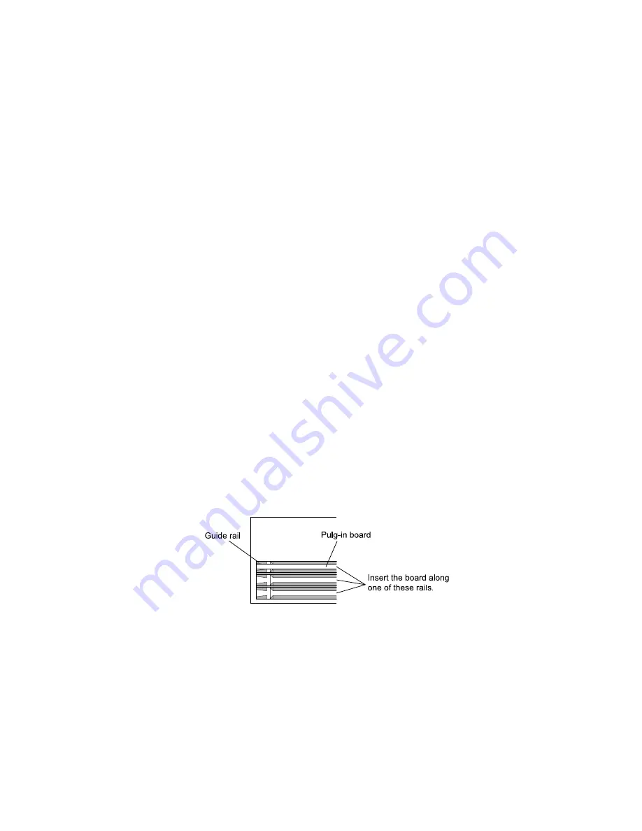
4. Insert the board along the guide rails about two-thirds of the way inside the MU128, with the connector side
face down and toward you (as shown below). Make sure to insert it slowly and gently, keeping the edges of
the board inside the proper guide rails, as shown in the illustration. With keeping the board in place, plug in
one of the three cable connectors to the connector on the XG Plug-in board. Any one of the cable connectors
can be used.
The logical board assignment in the MU128 (PLG-1 -3) is set automatically to the following order: 1) PLG100-
VL, 2) PLG100-DX, 3) PLG100-VH.
Summary of Contents for MU128
Page 7: ...7 7 7 7 7 MU128 MU128 MU128 MU128 MU128 28C99 8812612 LCD 28CA1 8812501 ...
Page 16: ...MU128 16 ...
Page 17: ...MU128 17 ...
Page 32: ...MU128 2 ...
Page 34: ...MU128 4 ...


