Test
LCD display
Test description, judging conditions, etc.
No.
009
009: Output L Chk
Checks the output level L. While sound is output, “ON” is displayed on the LCD.
•
Output Level and Cross Talk Level (PHONES)
Connect the level meter to the [PHONES] terminal (L and R).
Confirm each output level is as follows.
PHONES L: -4.6dBu ±2dB
PHONES R: -62.0dBu or less
•
Output Level and Cross Talk Level (OUTPUT)
Connect the level meter to the OUTPUT terminal ([L/MONO] and [R]). Insert the jacks to both
the [L/MONO] and [R] terminals at the same time.
Confirm each output level is as follows.
OUTPUT L: +1.4dBu ±2dB
OUTPUT R: -62.0dBu or less
Pull out the jack on the [R] terminal.
Confirm the output level is as follows.
OUTPUT L: -4.6dBu ±2dB
• Volume
Attenuation
Connect the level meter to the OUTPUT terminal ([L/MONO] and [R]). Insert the jacks to both
the [L/MONO] and [R] terminals at the same time.
Set the [MASTER VOLUME] knob to minimum, and measure the attenuation level.
Confirm the output level is as follows.
OUTPUT L: -62.0dBu or less
010
010: MUTE Chk
Checks the analog mute function.
•
Analog Mute (PHONES)
Connect the level meter to the [PHONES] terminal (L and R).
Press the [INC] switch, and the output signal is muted.
Confirm “MUTE ON” is displayed on the LCD and the output sound is muted.
Also, confirm each output level is as follows at that time.
PHONES L: -36.0dBu or less
PHONES R: -36.0dBu or less
•
Analog Mute (OUTPUT)
Connect the level meter to the OUTPUT terminal ([L/MONO] and [R]). Insert the jacks to both
the [L/MONO] and [R] terminals at the same time.
Press the [INC] switch, and the output signal is muted.
Confirm “MUTE ON” is displayed on the LCD and the output sound is muted.
Also, confirm each output level is as follows at that time.
OUTPUT L: -42.0dBu or less
OUTPUT R: -42.0dBu or less
011
011: SW, LED Chk
Checks the panel switches and LEDs.
Press the panel switch as indicated on the display. The corresponded LED lights.
If there are two or more corresponded LED, press the panel switch repeatedly, and each LED lights.
While pressing the panel switch, the corresponding pitch sound is output
and “switch name + On” is displayed on the LCD.
The inspection of the segment display is executed
by pressing “SELECT” switch once after the test is executed in general.
Confirm LED lights one by one. While executing this test,
“Now Executing” is displayed in blinking on the LCD.
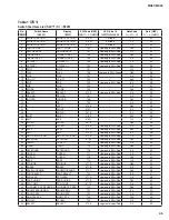
Refer to the “Switch Test Item List” (Table 1 on page 45) for the relationship between the switch number
and the generated pitch. Confirm LED lights one-by-one.
32
MX61/MX49

