2-11
1
2
3
4
5
6
7
8
9
10
PERIOD
IC
CHECK
S AN
D A
D
JU
STMEN
T
S
PERIODIC MAINTENANCE
6.
Adjust:
• Adjust to original set value
TIP
• When adjust valve clearance, record the measured read-
ing of current.
• Measure the valve clearance in the following sequence.
▼▼▼▼▼▼▼▼▼▼▼▼▼▼▼▼▼▼▼▼▼▼▼▼▼▼▼▼▼▼▼▼▼▼▼▼▼▼▼▼▼
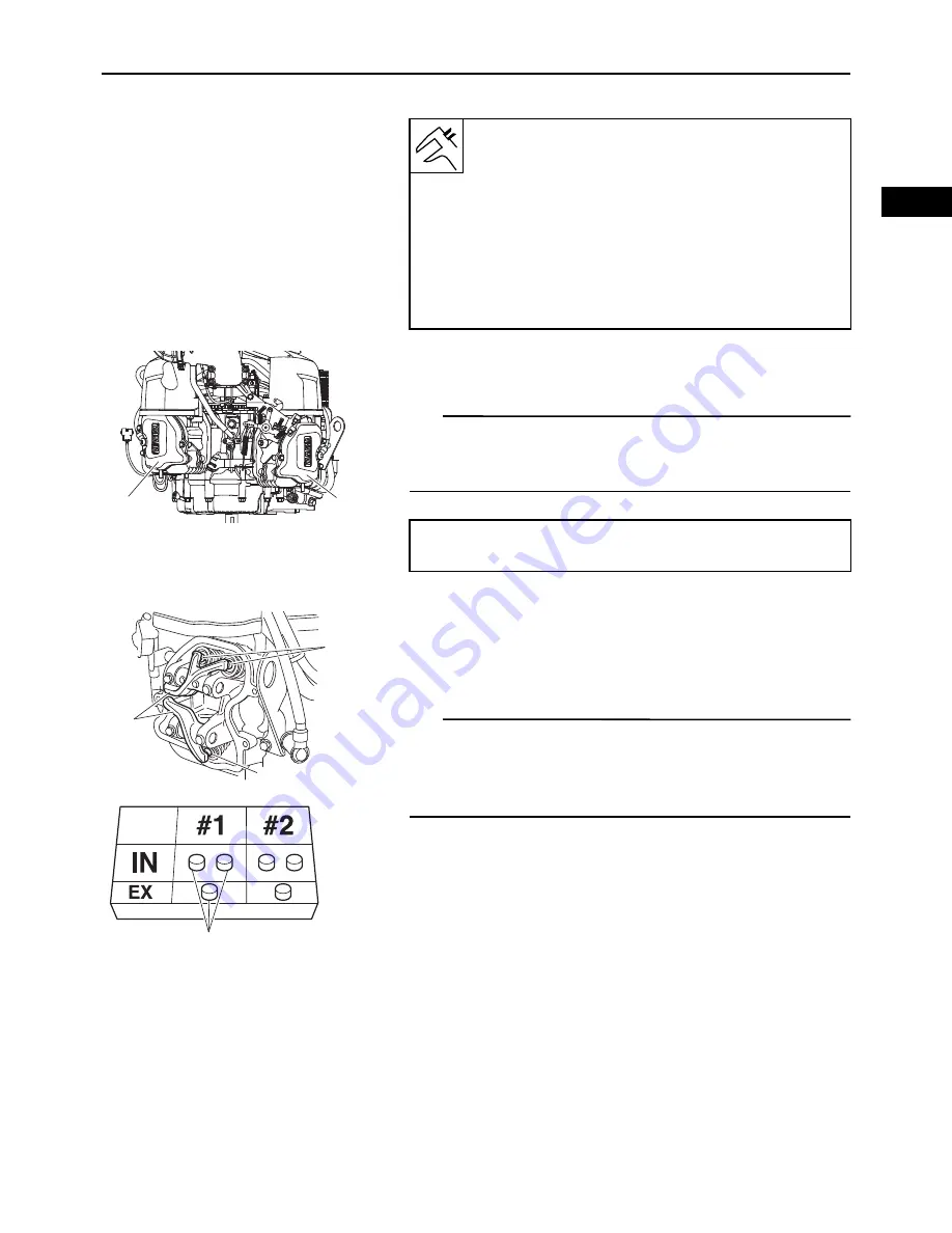
a. Remove the rocker arm “1” and the adjusting pad
“2”.
(Refer to “CYLINDER HEAD COVERS, CYLINDER
HEADS” on page 3-19)
TIP
• Pay attention so that the push rod does not fall into the
cylinder head.
• Make a note of the position of each adjusting pad “3” so
that they can be installed in the correct place.
b. Calculate the difference between the specified
valve clearance and the measured valve clearance.
Example:
Specified valve clearance = 0.07–0.13 mm (0.003–
0.005 in)
Measured valve clearance = 0.18 mm (0.007 in)
0.18 mm (0.007 in)–0.13 mm (0.005 in) = 0.05 mm
(0.002 in)
Valve clearance (cold)
Normal ENG operation range (between
1000 hr periodic maintenance):
Intake: 0.02–0.2 mm (0.0008–0.01 in)
Exhaust: 0.02–0.2 mm (0.0008–0.01 in)
Original set value (adjust at 1000 hr peri-
odic maintenance):
Intake: 0.07–0.13 mm (0.003–0.005 in)
Exhaust: 0.07–0.13 mm (0.003–0.005 in)
#1
#2
Valve clearance measuring sequence
Cylinder #2
#1
1
2
2
3
Summary of Contents for MX800V
Page 2: ...7UC F8197 E0_Hyoshi indd 3 4 2017 10 27 13 08 23 ...
Page 38: ...2 18 1 2 3 4 5 6 7 8 9 10 PERIODIC CHECKS AND ADJUSTMENTS PERIODIC MAINTENANCE MEMO ...
Page 94: ...3 56 1 2 3 4 5 6 7 8 9 10 ENGINE PISTONS CAMSHAFT CRANKCASE AND CRANKSHAFT MEMO ...
Page 103: ...4 9 1 2 3 4 5 6 7 8 9 10 FUEL INTAKE MANIFOLD MEMO ...
Page 106: ...5 3 1 2 3 4 5 6 7 8 9 10 ELECTRICAL ELECTRICAL COMPONENTS ELECTRICAL COMPONENTS 1 3 4 5 2 2 ...
Page 118: ...5 15 1 2 3 4 5 6 7 8 9 10 ELECTRICAL ELECTRIC STARTING SYSTEM MEMO ...
Page 140: ...7 14 1 2 3 4 5 6 7 8 9 10 SPECIFICATIONS WIRE ROUTING DIAGRAM ...
Page 142: ...7 16 1 2 3 4 5 6 7 8 9 10 SPECIFICATIONS WIRE ROUTING DIAGRAM LEFT SIDE VIEW ...
Page 144: ...7 18 1 2 3 4 5 6 7 8 9 10 SPECIFICATIONS WIRE ROUTING DIAGRAM RIGHT SIDE VIEW ...
Page 146: ...7 20 1 2 3 4 5 6 7 8 9 10 SPECIFICATIONS WIRE ROUTING DIAGRAM ...
Page 148: ...7 22 1 2 3 4 5 6 7 8 9 10 SPECIFICATIONS WIRE ROUTING DIAGRAM ...
Page 150: ...7 24 1 2 3 4 5 6 7 8 9 10 SPECIFICATIONS WIRE ROUTING DIAGRAM REAR SIDE VIEW ...
Page 152: ...7 26 1 2 3 4 5 6 7 8 9 10 SPECIFICATIONS WIRE ROUTING DIAGRAM ...
Page 156: ...MEMO ...
Page 157: ...7UC F8197 E0_Hyoshi indd 3 4 2017 10 27 13 08 23 ...


