2-12
1
2
3
4
5
6
7
8
9
10
PE
RIODIC
CHE
CKS AND ADJUSTMENTS
PERIODIC MAINTENANCE
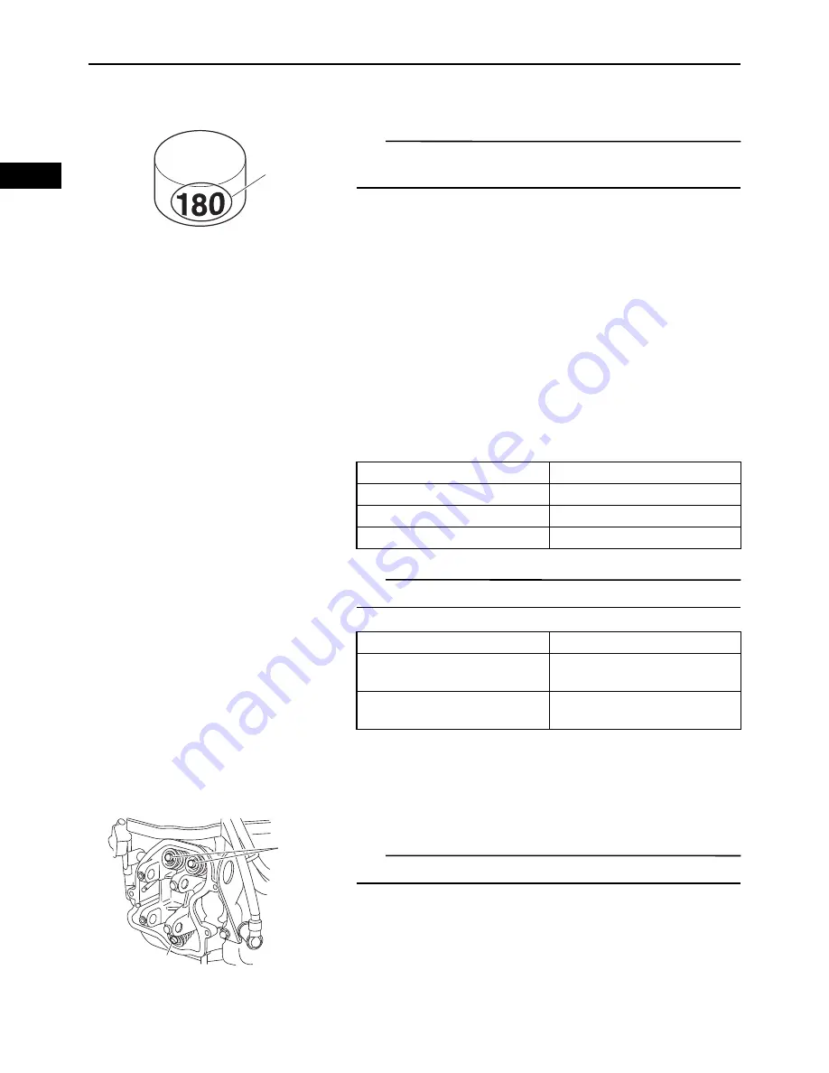
c. Check the thickness of the current adjusting pad.
TIP
The thickness of each adjusting pad is indicated in 1/100
mm units “a” and inscribed on the side.
Example:
If the adjusting pad is marked “180”, the pad thick-
ness is 1.80 mm (0.071 in).
d. Calculate the sum of the values obtained in steps
(b) and (c) to determine the required adjusting pad
thickness and the adjusting pad number.
Example:
1.80 mm (0.071 in) + 0.05 mm (0.002 in) = 1.85 mm
(0.073 in)
The adjusting pad number is 185.
e. Round off the adjusting pad number according to
the following table, and then select the suitable
adjusting pad.
TIP
Refer to the following table for the available adjusting pads.
Example:
Adjusting pad number = 188
Rounded value = 200
New adjusting pad number = 200
f. Install the new adjusting pad “4”.
TIP
Lubricate the adjusting pad with engine oil.
a
Last digit
Rounded value
0, 2
0
5
5
8
10
Adjusting pad range
Nos. 180–300
Adjusting pad thickness
1.80–3.00 mm
(0.07086–0.11811 in)
Available adjusting pads
0.050 mm (0.002 in) incre-
ments
4
4
Summary of Contents for MX800V
Page 2: ...7UC F8197 E0_Hyoshi indd 3 4 2017 10 27 13 08 23 ...
Page 38: ...2 18 1 2 3 4 5 6 7 8 9 10 PERIODIC CHECKS AND ADJUSTMENTS PERIODIC MAINTENANCE MEMO ...
Page 94: ...3 56 1 2 3 4 5 6 7 8 9 10 ENGINE PISTONS CAMSHAFT CRANKCASE AND CRANKSHAFT MEMO ...
Page 103: ...4 9 1 2 3 4 5 6 7 8 9 10 FUEL INTAKE MANIFOLD MEMO ...
Page 106: ...5 3 1 2 3 4 5 6 7 8 9 10 ELECTRICAL ELECTRICAL COMPONENTS ELECTRICAL COMPONENTS 1 3 4 5 2 2 ...
Page 118: ...5 15 1 2 3 4 5 6 7 8 9 10 ELECTRICAL ELECTRIC STARTING SYSTEM MEMO ...
Page 140: ...7 14 1 2 3 4 5 6 7 8 9 10 SPECIFICATIONS WIRE ROUTING DIAGRAM ...
Page 142: ...7 16 1 2 3 4 5 6 7 8 9 10 SPECIFICATIONS WIRE ROUTING DIAGRAM LEFT SIDE VIEW ...
Page 144: ...7 18 1 2 3 4 5 6 7 8 9 10 SPECIFICATIONS WIRE ROUTING DIAGRAM RIGHT SIDE VIEW ...
Page 146: ...7 20 1 2 3 4 5 6 7 8 9 10 SPECIFICATIONS WIRE ROUTING DIAGRAM ...
Page 148: ...7 22 1 2 3 4 5 6 7 8 9 10 SPECIFICATIONS WIRE ROUTING DIAGRAM ...
Page 150: ...7 24 1 2 3 4 5 6 7 8 9 10 SPECIFICATIONS WIRE ROUTING DIAGRAM REAR SIDE VIEW ...
Page 152: ...7 26 1 2 3 4 5 6 7 8 9 10 SPECIFICATIONS WIRE ROUTING DIAGRAM ...
Page 156: ...MEMO ...
Page 157: ...7UC F8197 E0_Hyoshi indd 3 4 2017 10 27 13 08 23 ...


