3-27
1
2
3
4
5
6
7
8
9
10
ENGINE
VALVES
REMOVING THE VALVES AND VALVE SPRINGS
The following procedure applies to all of the valves, valve
springs and related components.
1.
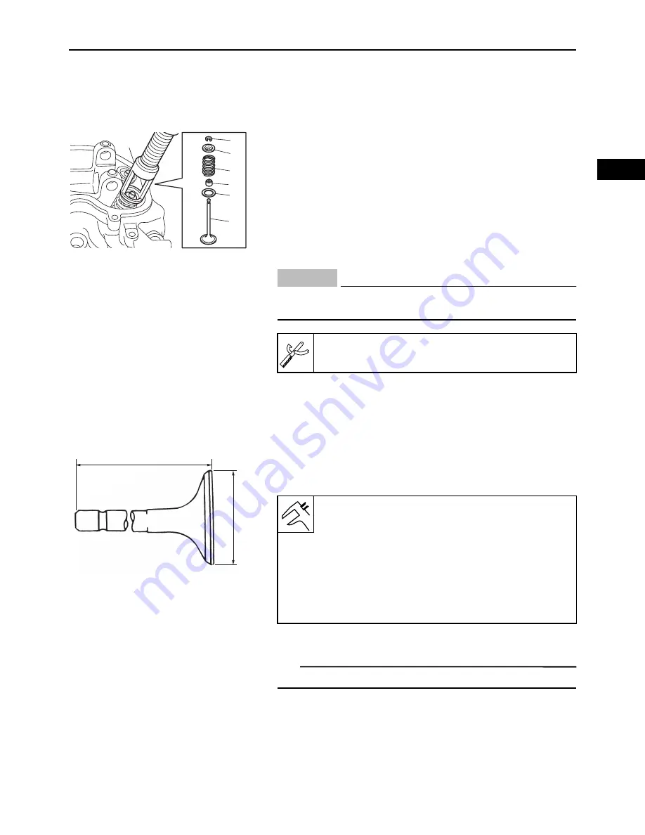
Remove:
• Valve cotter “1”
• Valve spring retainer “2”
• Valve spring “3”
• Valve stem seal “4”
• Valve spring seat “5”
• Valve “6”
Remove the parts using the valve spring compres-
sor “7”.
CHECKING THE VALVES AND VALVE SPRINGS
The following procedure applies to all of the valves, valve
springs and related components.
1.
Measure:
• Valve stem length “a”
• Valve head diameter “b”
Out of specifications
Replace.
TIP
Intake and exhaust springs are different. Do not mix.
1
2
3
4
5
6
7
Do not compress the valve spring more than neces-
sary.
Valve spring compressor:
90890-01253
NOTICE
b
a
Valve stem length (Intake):
88.8 mm (3.4961 in)
Valve stem length (Exhaust):
89.8 mm (3.5354 in)
Valve head diameter (Intake):
27.9–28.1 mm (1.0984–1.1063 in)
Valve head diameter (Exhaust):
34.9–35.1 mm (1.3740–1.3819 in)
Summary of Contents for MX800V
Page 2: ...7UC F8197 E0_Hyoshi indd 3 4 2017 10 27 13 08 23 ...
Page 38: ...2 18 1 2 3 4 5 6 7 8 9 10 PERIODIC CHECKS AND ADJUSTMENTS PERIODIC MAINTENANCE MEMO ...
Page 94: ...3 56 1 2 3 4 5 6 7 8 9 10 ENGINE PISTONS CAMSHAFT CRANKCASE AND CRANKSHAFT MEMO ...
Page 103: ...4 9 1 2 3 4 5 6 7 8 9 10 FUEL INTAKE MANIFOLD MEMO ...
Page 106: ...5 3 1 2 3 4 5 6 7 8 9 10 ELECTRICAL ELECTRICAL COMPONENTS ELECTRICAL COMPONENTS 1 3 4 5 2 2 ...
Page 118: ...5 15 1 2 3 4 5 6 7 8 9 10 ELECTRICAL ELECTRIC STARTING SYSTEM MEMO ...
Page 140: ...7 14 1 2 3 4 5 6 7 8 9 10 SPECIFICATIONS WIRE ROUTING DIAGRAM ...
Page 142: ...7 16 1 2 3 4 5 6 7 8 9 10 SPECIFICATIONS WIRE ROUTING DIAGRAM LEFT SIDE VIEW ...
Page 144: ...7 18 1 2 3 4 5 6 7 8 9 10 SPECIFICATIONS WIRE ROUTING DIAGRAM RIGHT SIDE VIEW ...
Page 146: ...7 20 1 2 3 4 5 6 7 8 9 10 SPECIFICATIONS WIRE ROUTING DIAGRAM ...
Page 148: ...7 22 1 2 3 4 5 6 7 8 9 10 SPECIFICATIONS WIRE ROUTING DIAGRAM ...
Page 150: ...7 24 1 2 3 4 5 6 7 8 9 10 SPECIFICATIONS WIRE ROUTING DIAGRAM REAR SIDE VIEW ...
Page 152: ...7 26 1 2 3 4 5 6 7 8 9 10 SPECIFICATIONS WIRE ROUTING DIAGRAM ...
Page 156: ...MEMO ...
Page 157: ...7UC F8197 E0_Hyoshi indd 3 4 2017 10 27 13 08 23 ...

