5-5
1
2
3
4
5
6
7
8
9
10
ELECTRICAL
ELECTRICAL COMPONENTS
CHECKING THE SWITCH CONTINUITY
Check each switch for continuity with the tester. If the con-
tinuity reading is incorrect, check the wiring connections
and if necessary, replace the switch.
TIP
• Before checking for continuity, set the digital circuit tester
to the “
” range.
• When checking for continuity, switch back and forth
between the switch positions a few times.
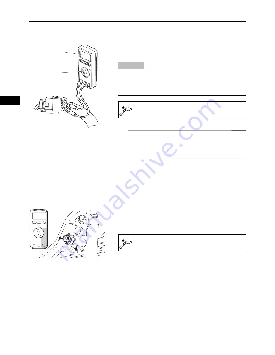
CHECKING THE OIL PRESSURE SWITCH
1.
Drain:
• Engine oil
2.
Disconnect:
• Oil pressure switch lead
3.
Connect:
• Digital circuit tester
(between the engine ground and oil pressure switch
terminal)
4.
Check:
• Oil pressure switch continuity
No continuity
Replace the oil pressure switch.
CHECKING THE TCI UNIT RESISTANCE
The following procedure applies to all of the TCI units.
1.
Check:
• Coil resistance
Out of specification
Replace.
Ω”
”
O.L”
”
Never insert the tester probes into the coupler termi-
nal slots. Always insert the probes from the opposite
end of the coupler, taking care not to loosen or dam-
age the leads.
Model 88 Multimeter with tachometer:
YU-A1927
NOTICE
Model 88 Multimeter with tachometer:
YU-A1927
Summary of Contents for MX800V
Page 2: ...7UC F8197 E0_Hyoshi indd 3 4 2017 10 27 13 08 23 ...
Page 38: ...2 18 1 2 3 4 5 6 7 8 9 10 PERIODIC CHECKS AND ADJUSTMENTS PERIODIC MAINTENANCE MEMO ...
Page 94: ...3 56 1 2 3 4 5 6 7 8 9 10 ENGINE PISTONS CAMSHAFT CRANKCASE AND CRANKSHAFT MEMO ...
Page 103: ...4 9 1 2 3 4 5 6 7 8 9 10 FUEL INTAKE MANIFOLD MEMO ...
Page 106: ...5 3 1 2 3 4 5 6 7 8 9 10 ELECTRICAL ELECTRICAL COMPONENTS ELECTRICAL COMPONENTS 1 3 4 5 2 2 ...
Page 118: ...5 15 1 2 3 4 5 6 7 8 9 10 ELECTRICAL ELECTRIC STARTING SYSTEM MEMO ...
Page 140: ...7 14 1 2 3 4 5 6 7 8 9 10 SPECIFICATIONS WIRE ROUTING DIAGRAM ...
Page 142: ...7 16 1 2 3 4 5 6 7 8 9 10 SPECIFICATIONS WIRE ROUTING DIAGRAM LEFT SIDE VIEW ...
Page 144: ...7 18 1 2 3 4 5 6 7 8 9 10 SPECIFICATIONS WIRE ROUTING DIAGRAM RIGHT SIDE VIEW ...
Page 146: ...7 20 1 2 3 4 5 6 7 8 9 10 SPECIFICATIONS WIRE ROUTING DIAGRAM ...
Page 148: ...7 22 1 2 3 4 5 6 7 8 9 10 SPECIFICATIONS WIRE ROUTING DIAGRAM ...
Page 150: ...7 24 1 2 3 4 5 6 7 8 9 10 SPECIFICATIONS WIRE ROUTING DIAGRAM REAR SIDE VIEW ...
Page 152: ...7 26 1 2 3 4 5 6 7 8 9 10 SPECIFICATIONS WIRE ROUTING DIAGRAM ...
Page 156: ...MEMO ...
Page 157: ...7UC F8197 E0_Hyoshi indd 3 4 2017 10 27 13 08 23 ...


