IMPORTANT INFORMATION
1-6
1
2
3
4
5
6
7
8
9
10
GEN
E
RAL I
N
FOR
M
A
T
ION
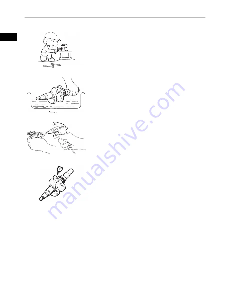
Tightening torque
Be sure to follow torque specifications. When tightening
bolts, nuts or screws, start with the largest-diameter fas-
tener and work from an inner position to an outer position
in a crisscross pattern.
Notes on disassembly and assembly
• Parts should be cleaned in solvent and blown dry with
compressed air after disassembly.
• Contact surfaces of moving parts should be oiled when
reassembled.
• Make sure that the parts, move smoothly after each sec-
tion of the machine is assembled.
ALL REPLACEMENT PARTS
We recommend the use of genuine Yamaha parts for all
replacements. Use oil and/or grease, recommended by
Yamaha, for assembly and adjustment.
GASKETS, OIL SEALS, AND O-RINGS
1.
All gaskets, seals, and O-rings should be replaced
when an engine is overhauled. All gaskets surfaces,
oil seal lips, and O-rings must be cleaned.
2.
Properly oil all mating parts and bearings during reas-
sembly. Apply grease to the oil seal lips.
Summary of Contents for MX800V
Page 2: ...7UC F8197 E0_Hyoshi indd 3 4 2017 10 27 13 08 23 ...
Page 38: ...2 18 1 2 3 4 5 6 7 8 9 10 PERIODIC CHECKS AND ADJUSTMENTS PERIODIC MAINTENANCE MEMO ...
Page 94: ...3 56 1 2 3 4 5 6 7 8 9 10 ENGINE PISTONS CAMSHAFT CRANKCASE AND CRANKSHAFT MEMO ...
Page 103: ...4 9 1 2 3 4 5 6 7 8 9 10 FUEL INTAKE MANIFOLD MEMO ...
Page 106: ...5 3 1 2 3 4 5 6 7 8 9 10 ELECTRICAL ELECTRICAL COMPONENTS ELECTRICAL COMPONENTS 1 3 4 5 2 2 ...
Page 118: ...5 15 1 2 3 4 5 6 7 8 9 10 ELECTRICAL ELECTRIC STARTING SYSTEM MEMO ...
Page 140: ...7 14 1 2 3 4 5 6 7 8 9 10 SPECIFICATIONS WIRE ROUTING DIAGRAM ...
Page 142: ...7 16 1 2 3 4 5 6 7 8 9 10 SPECIFICATIONS WIRE ROUTING DIAGRAM LEFT SIDE VIEW ...
Page 144: ...7 18 1 2 3 4 5 6 7 8 9 10 SPECIFICATIONS WIRE ROUTING DIAGRAM RIGHT SIDE VIEW ...
Page 146: ...7 20 1 2 3 4 5 6 7 8 9 10 SPECIFICATIONS WIRE ROUTING DIAGRAM ...
Page 148: ...7 22 1 2 3 4 5 6 7 8 9 10 SPECIFICATIONS WIRE ROUTING DIAGRAM ...
Page 150: ...7 24 1 2 3 4 5 6 7 8 9 10 SPECIFICATIONS WIRE ROUTING DIAGRAM REAR SIDE VIEW ...
Page 152: ...7 26 1 2 3 4 5 6 7 8 9 10 SPECIFICATIONS WIRE ROUTING DIAGRAM ...
Page 156: ...MEMO ...
Page 157: ...7UC F8197 E0_Hyoshi indd 3 4 2017 10 27 13 08 23 ...


