1
2
3
4
5
6
7
8
9
10
ENGINE
3-1
ENGINE
ENGINE INSPECTION
MEASURING THE COMPRESSION PRESSURE
The following procedure applies to all of the cylinders.
TIP
Measure the compression pressure after checking and
adjusting the valve clearance.
1.
Warm up the engine for several minutes.
2.
Remove:
• Spark plug cap
• Spark plug
3.
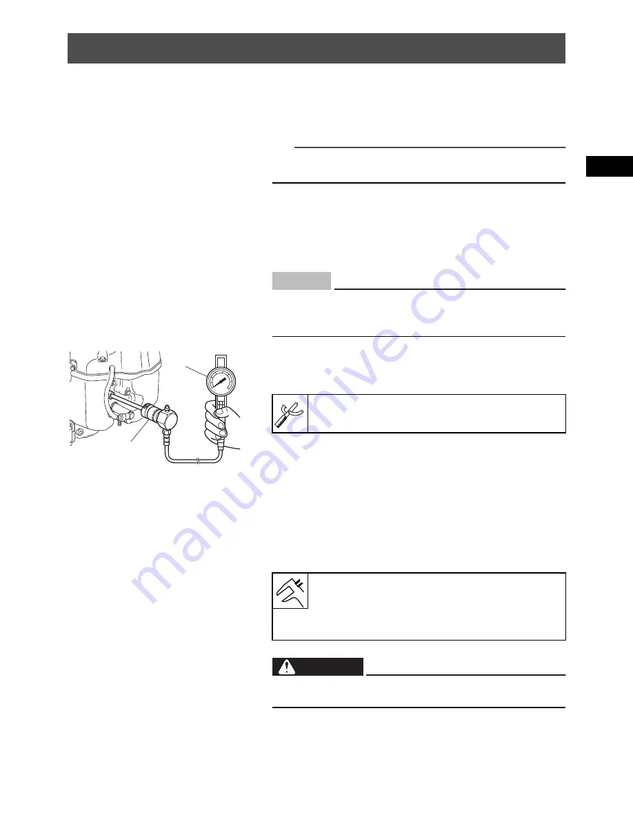
Connect:
• Engine compression tester “1”
• Extension “2”
4.
Measure:
• Compression pressure
Open the throttle and crank the engine until the
needle stop rising on the engine compression tes-
ter.
Out of specification
Refer to steps (a) and (b).
Before removing the spark plug, use compressed air
to clean the cylinder head cover to prevent dirt from
falling into the engine.
NOTICE
1
2
Engine compression tester:
YU-33223
Standard compression pressure:
490–640 kPa (4.9–6.4 kg/cm², 71–93 psi)
Limit:
430 kPa (4.3 kg/cm², 62 psi)
To prevent sparking the plugs, remove all TCI units
connectors before cranking the engine.
WARNING
Summary of Contents for MX800V
Page 2: ...7UC F8197 E0_Hyoshi indd 3 4 2017 10 27 13 08 23 ...
Page 38: ...2 18 1 2 3 4 5 6 7 8 9 10 PERIODIC CHECKS AND ADJUSTMENTS PERIODIC MAINTENANCE MEMO ...
Page 94: ...3 56 1 2 3 4 5 6 7 8 9 10 ENGINE PISTONS CAMSHAFT CRANKCASE AND CRANKSHAFT MEMO ...
Page 103: ...4 9 1 2 3 4 5 6 7 8 9 10 FUEL INTAKE MANIFOLD MEMO ...
Page 106: ...5 3 1 2 3 4 5 6 7 8 9 10 ELECTRICAL ELECTRICAL COMPONENTS ELECTRICAL COMPONENTS 1 3 4 5 2 2 ...
Page 118: ...5 15 1 2 3 4 5 6 7 8 9 10 ELECTRICAL ELECTRIC STARTING SYSTEM MEMO ...
Page 140: ...7 14 1 2 3 4 5 6 7 8 9 10 SPECIFICATIONS WIRE ROUTING DIAGRAM ...
Page 142: ...7 16 1 2 3 4 5 6 7 8 9 10 SPECIFICATIONS WIRE ROUTING DIAGRAM LEFT SIDE VIEW ...
Page 144: ...7 18 1 2 3 4 5 6 7 8 9 10 SPECIFICATIONS WIRE ROUTING DIAGRAM RIGHT SIDE VIEW ...
Page 146: ...7 20 1 2 3 4 5 6 7 8 9 10 SPECIFICATIONS WIRE ROUTING DIAGRAM ...
Page 148: ...7 22 1 2 3 4 5 6 7 8 9 10 SPECIFICATIONS WIRE ROUTING DIAGRAM ...
Page 150: ...7 24 1 2 3 4 5 6 7 8 9 10 SPECIFICATIONS WIRE ROUTING DIAGRAM REAR SIDE VIEW ...
Page 152: ...7 26 1 2 3 4 5 6 7 8 9 10 SPECIFICATIONS WIRE ROUTING DIAGRAM ...
Page 156: ...MEMO ...
Page 157: ...7UC F8197 E0_Hyoshi indd 3 4 2017 10 27 13 08 23 ...


