3-24
1
2
3
4
5
6
7
8
9
10
ENGINE
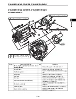
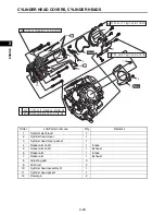
CYLINDER HEAD COVERS, CYLINDER HEADS
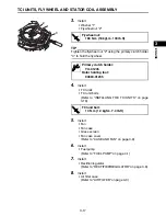
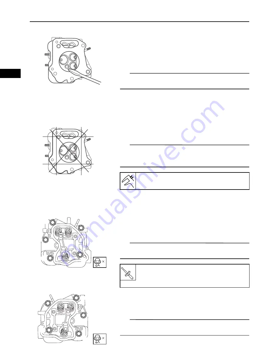
1.
Check:
• Cylinder head combustion chamber
Check the combustion chamber for carbon depos-
its.
Any carbon deposits
Eliminate.
TIP
Be sure not to damage the sealing surface of the cylinder
head.
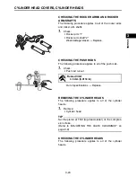
2.
Check:
• Cylinder head
Cracks/damage around the hole of spark plug
Replace.
3.
Measure:
• Cylinder head warpage
TIP
Measure the warpage on the contact surface of the cylin-
der head at six points using the straight edge and feeler
gauge set.
Out of specifications
Resurface or replace.
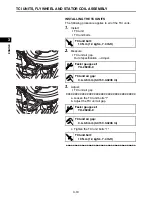
INSTALLING THE CYLINDER HEAD ASSEMBLY
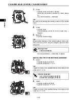
1.
Install:
• Cylinder head assembly #1
• Cylinder head bolts “1” to “5”
TIP
Tighten the bolts to the specified torque in two steps and in
order from “1” to “5”.
2.
Install:
• Cylinder head assembly #2
• Cylinder head bolts “1” to “5”
TIP
Tighten the bolts to the specified torque in two steps and in
order from “1” to “5”.
Warpage limit:
0.05 mm (0.002 in)
1
2
3
4
5
5
Cylinder head bolt:
1st: 12 N·m (1.2 kgf·m, 8.9 lb·ft)
2nd: 50 N·m (5.0 kgf·m, 37 lb·ft)
T
R
.
.
1
2
3
4
5
5
Summary of Contents for MX800V
Page 2: ...7UC F8197 E0_Hyoshi indd 3 4 2017 10 27 13 08 23 ...
Page 38: ...2 18 1 2 3 4 5 6 7 8 9 10 PERIODIC CHECKS AND ADJUSTMENTS PERIODIC MAINTENANCE MEMO ...
Page 94: ...3 56 1 2 3 4 5 6 7 8 9 10 ENGINE PISTONS CAMSHAFT CRANKCASE AND CRANKSHAFT MEMO ...
Page 103: ...4 9 1 2 3 4 5 6 7 8 9 10 FUEL INTAKE MANIFOLD MEMO ...
Page 106: ...5 3 1 2 3 4 5 6 7 8 9 10 ELECTRICAL ELECTRICAL COMPONENTS ELECTRICAL COMPONENTS 1 3 4 5 2 2 ...
Page 118: ...5 15 1 2 3 4 5 6 7 8 9 10 ELECTRICAL ELECTRIC STARTING SYSTEM MEMO ...
Page 140: ...7 14 1 2 3 4 5 6 7 8 9 10 SPECIFICATIONS WIRE ROUTING DIAGRAM ...
Page 142: ...7 16 1 2 3 4 5 6 7 8 9 10 SPECIFICATIONS WIRE ROUTING DIAGRAM LEFT SIDE VIEW ...
Page 144: ...7 18 1 2 3 4 5 6 7 8 9 10 SPECIFICATIONS WIRE ROUTING DIAGRAM RIGHT SIDE VIEW ...
Page 146: ...7 20 1 2 3 4 5 6 7 8 9 10 SPECIFICATIONS WIRE ROUTING DIAGRAM ...
Page 148: ...7 22 1 2 3 4 5 6 7 8 9 10 SPECIFICATIONS WIRE ROUTING DIAGRAM ...
Page 150: ...7 24 1 2 3 4 5 6 7 8 9 10 SPECIFICATIONS WIRE ROUTING DIAGRAM REAR SIDE VIEW ...
Page 152: ...7 26 1 2 3 4 5 6 7 8 9 10 SPECIFICATIONS WIRE ROUTING DIAGRAM ...
Page 156: ...MEMO ...
Page 157: ...7UC F8197 E0_Hyoshi indd 3 4 2017 10 27 13 08 23 ...


