background image

OWNER’S MANUAL

MODE D’EMPLOI

BEDIENUNGSANLEITUNG

BRUKSANVISNING

MANUALE DI ISTRUZIONI

MANUAL DE INSTRUCCIONES

GEBRUIKSAANWIJZING

Natural Sound Speaker Package System

Jeu d’enceintes “Son Naturel”

Natural-Sound-Lautsprechersystem

Natural Sound högtalarpaket

Sistema completo di altoparlanti a suono naturale

Paquete del sistema de altavoces con sonido natural

Natural Sound Luidsprekerpakket Systeem

NS-P400

Active Servo

Technology

G A R

Summary of Contents for NS-C40

Page 1: ...KSAANWIJZING Natural Sound Speaker Package System Jeu d enceintes Son Naturel Natural Sound Lautsprechersystem Natural Sound högtalarpaket Sistema completo di altoparlanti a suono naturale Paquete del sistema de altavoces con sonido natural Natural Sound Luidsprekerpakket Systeem NS P400 Active Servo Technology G A R ...

Page 2: ...mbale el aparato y verificar que los siguientes accesorios están en la caja BIJGELEVERDE ACCESSOIRES Controleer na het uitpakken of de volgende onderdelen voorhanden zijn Speaker cords Câbles d enceintes Lautsprecheranschlußkabel Högtalarledningar Cavi per gli altoparlanti Cables de los altavoces Luidsprekerdraden Rubber Pads for SW P40 Tampons en caoutchouc pour SW P40 Gummiunterlagen für SW P40 ...

Page 3: ...M CONTENTS Main speakers NS M40 2 Way Acoustic Suspension Speaker System Center speaker NS C40 Full range Acoustic Suspension Speaker System Effect speakers NS E40 Full range Acoustic Suspension Speaker System Subwoofer SW P40 Active Servo Processing Subwoofer System with a built in power amplifier This subwoofer system employs YAMAHA Active Servo Technology which YAMAHA developed for reproducing ...

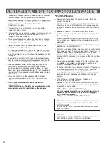
Page 4: ...ction wires When moving the unit first disconnect the power plug and the wires connected to other equipment Never pull the wire itself Be sure to read the TROUBLESHOOTING section regarding common operating errors before concluding that the unit is faulty When not planning to use this unit for long periods of time ie vacation etc disconnect the AC power plug from the wall outlet To prevent lightnin...

Page 5: ...ect sounds The effect speakers are used for the effect and surround sounds and the center speaker is for the center sounds dialog etc The subwoofer is for reinforcing low frequencies on your audio system Placing speakers Main speakers On both sides of the TV and in almost the same height as the TV Effect speakers Behind your listening position facing slightly inward Nearly 1 8 m approx 6 feet up f...

Page 6: ...e There may be a case that you cannot obtain enough super bass sounds from this unit when listening at the middle of the room This is because standing waves have developed between two parallel walls and the bass sounds are being canceled In such a case face the subwoofer obliquely to the wall It also may be necessary to break up the parallel surfaces by placing bookshelves etc along the walls Use ...

Page 7: ...nd vibrations may cause them to fall down To avoid accidents resulting from tripping over loose speaker cords fix them to the wall 7 English Holes Screen 40mm 2mm Min 12mm Diam 4 5mm Tapping screw Available at the hardware store Wall wall support 1 2 Mounting the center speaker Place the center speaker on top of the TV or on the floor under the TV or inside the TV rack so that it is stabilized Whe...

Page 8: ...this section which is suitable for your audio system Also refer to the owner s manual for each component to be connected to this unit CONNECTIONS OUTPUT TO SPEAKERS INPUT1 FROM AMPLIFIER INPUT2 ON OFF AUTO POWER OUTPUT TO SPEAKERS INPUT1 FROM AMPLIFIER REAR REAR CENTER CAUTION SEE INSTRUCTION MANUAL FOR CORRECT SETTING MAIN SPEAKERS A B REAR SINGLE Subwoofer Effect speaker Center speaker Effect sp...

Page 9: ...to connect speaker cords to the input terminals of the speakers except the subwoofer How to connect speaker cords to the subwoofer s OUTPUT INPUT1 terminals For connections cut the speaker wires as short as possible If the connections are faulty no sound will be heard from the speakers How to Connect Red positive Black negative Unscrew the knob Insert the bare wire Remove approx 10 mm 3 8 insulati...

Page 10: ... ON OFF AUTO POWER OUTPUT TO SPEAKERS INPUT1 FROM AMPLIFIER INPUT2 ON OFF AUTO POWER Amplifier To AC outlet Connect the speaker output terminals of the amplifier to the INPUT1 terminals of the subwoofer and connect the OUTPUT terminals of the subwoofer to the main speakers Subwoofer Main speaker Main speaker Right Left ...

Page 11: ...eft L or right R INPUT2 terminal of the subwoofer To connect the subwoofer to the SPLIT SUBWOOFER terminals on the rear of the DSP amplifier connect them to both of the left L and right R INPUT2 terminals of the subwoofer OUTPUT TO SPEAKERS INPUT1 FROM AMPLIFIER INPUT2 ON OFF AUTO POWER INPUT2 ON OFF AUTO POWER PRE OUT SPLIT SUBWOOFER LOW PASS SUBWOOFER Pin plug cords Amplifier To AC outlet To con...

Page 12: ... off point Frequencies higher than the frequency selected by this control are all cut off and not output One graduation of this control represents 10 Hz Automatic power ON OFF function When you play a source the power to this unit turns on automatically by sensing audio signals input to this unit This unit turns into the standby mode automatically if the source being played is stopped or the input...

Page 13: ...f you change the main speakers NS M40 to others you must make this adjustment again For adjusting the VOLUME control and the HIGH CUT control refer to FREQUENCY CHARACTERISTICS on the next page Note about setting the HIGH CUT control This system is designed so that the optimum tone balance between the subwoofer and the main speakers is obtained when this control is set at the point of 80 Hz Howeve...

Page 14: ... Following figures show the optimum adjustment of each control and the frequency characteristics when this subwoofer is combined with NS M40 Frequency characteristics of this subwoofer SW P40 When combined with NS M40 VOLUME 0 I0 HIGH CUT 50Hz I50Hz 20 50 100 200 500Hz 40 50 60 70 80 90 dB HIGH CUT 50 Hz HIGH CUT 100 Hz HIGH CUT 150 Hz 20 50 100 200 500Hz 40 50 60 70 80 90 dB SW 2 NS M40 SW P40 ...

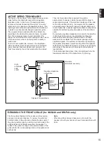
Page 15: ...edance output drive amplifier for subtracting output impedance of the amplifier is used By employing negative impedance drive circuits the amplifier is able to generate precise low amplitude low frequency waves with superior damping characteristics and these waves are then radiated from the cabinet opening as high amplitude signals The system can therefore by employing the negative impedance outpu...

Page 16: ...hem securely Connect them correctly that is to say L left to L R right to R to and to Play a source sound with bass frequencies Set the HIGH CUT control to a higher position Turn the knob to right Re position the subwoofer or break up the parallel surface by placing bookshelves etc along the walls Turn the POWER switch on Increase the level of input signal on the source Increase the level of input...

Page 17: ...1 mm x 281 mm x 188 5 mm 6 3 4 x 11 1 16 x 7 7 16 NS C40 436 mm x 131 mm x 210 5 mm 17 3 16 x 5 3 16 x 8 5 16 NS E40 171 mm x 281 mm x 112 mm 6 3 4 x 11 1 16 x 4 7 16 Weight NS M40 2 5 kg 5 lbs 8 oz x 2 NS C40 3 2 kg 7 lbs 1 oz NS E40 1 6 kg 3 lbs 8 oz x 2 SW P40 Type Active Servo Processing Subwoofer System Magnetically shielded type Speaker Unit 20 cm 7 7 8 cone woofer Amplifier Output 50W 5 ohm...

Page 18: ... RELLINGEN BEI HAMBURG F R OF GERMANY YAMAHA ELECTRONIQUE FRANCE S A RUE AMBROISE CROIZAT BP70 CROISSY BEAUBOURG 77312 MARNE LA VALLEE CEDEX02 FRANCE YAMAHA ELECTRONICS UK LTD YAMAHA HOUSE 200 RICKMANSWORTH ROAD WATFORD HERTS WD1 7JS ENGLAND YAMAHA SCANDINAVIA A B J A WETTERGRENS GATA 1 BOX 30053 400 43 VÄSTRA FRÖLUNDA SWEDEN YAMAHA MUSIC AUSTRALIA PTY LTD 17 33 MARKET ST SOUTH MELBOURNE 3205 VIC ...

Reviews: