background image

3

 En

Caution:

 Make sure the power cables for the subwoofer and your other AV components are disconnected from the 

AC wall outlets before making any connections.

Connection diagram

Preparing the speaker cables

Once you’ve positioned the speakers, you’ll need to cut 
the 25-meter (82 ft.) speaker cable to make five cables 
for connecting the two front speakers, center speaker, 
and the two surround speakers. 

1

Cut the included speaker cable to suitable 
lengths for the front, center, and surround 
speakers. You need five cables.

2

Remove about 10 mm (3/8") of insulation from 
the end of each speaker cable.

3

Twist the bare wires tightly.

Notes 

• Make the speaker cables as short as possible. Do not 

bundle or roll up excess cable.

• Twist the bare wires tightly so the individual strands 

are not splayed.

• Be careful not to injure yourself while preparing the 

speaker cables.

Connecting the speakers

ANTENNA

FM

GND AM

COMPONENT

VIDEO

P

R

P

B

Y

OPTICAL

( TV )

AV 1

AV 2

AV 3

AV 4

AV 5

AUDIO 1

AUDIO 2

COAXIAL

(CD)

COAXIAL

OPTICAL

VIDEO

CENTER

S

URROUND

HDMI 1

(BD/DVD)

HDMI 2

HDMI 3

HDMI 4

FRONT

COMPONENT

VIDEO

MONITOR OUT

P

R

P

B

Y

HDMI OUT

MONITOR OUT

AV

OUT

S

UBWOOFER

AUDIO

OUT

75

S

PEAKER

S

DOCK

CENTER

S

URROUND

FRONT

S

UBWOOFER

S

PEAKER

S

To AC wall outlet

Center speaker

Subwoofer

Amplifier

Front speakers

Right

Left

Surround speakers

Right

Left

Note: The 
exact layout of 
the speaker 
terminals 
depends on 
your amplifier.

Good

No Good

10 mm (3/8")

Summary of Contents for NS-P20

Page 1: ...SPEAKER PACKAGE RL OWNER S MANUAL MANUAL DE INSTRUCCIONES NS P20 NS B20 NS C20 NS SW20 ...

Page 2: ... first disconnect the power plug and the wires connected to other equipment Never pull the wires themselves 3 Never put a hand or a foreign object into the port located on the right side of this unit When moving this unit do not hold the port as it might cause personal injury and or damage to this unit 4 Since this unit has a built in power amplifier heat radiates from the rear panel Place the uni...

Page 3: ...rce as long as it is connected to the wall outlet even if this unit itself is turned off In this state this unit is designed to consume a very small quantity of power IMPORTANT THE WIRES IN MAINS LEAD ARE COLOURED IN ACCORDANCE WITH THE FOLLOWING CODE Blue NEUTRAL Brown LIVE As the colours of the wires in the mains lead of this apparatus may not correspond with the coloured markings identifying th...

Page 4: ...ontents 1 Installing the speakers 1 Installing the front center and surround speakers 2 Installing the subwoofer 2 Wall mounting the speakers 2 Connecting the speakers 3 Connection diagram 3 Connecting the power cables 4 Using the Subwoofer 4 Setting the subwoofer volume 4 Troubleshooting 5 Specifications 6 Package contents Speaker cable 25 m 82 ft x1 To be cut into 5 lengths for the front center ...

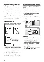
Page 5: ...essary to break up parallel wall surfaces by placing bookshelves etc along them Wall mounting the speakers You can mount the speakers on the wall as follows 1 Install screws into a solid wall or wall support as shown below Use 3 5 to 4 mm 1 8 diameter self tapping screws 2 Hang each speaker by its keyhole slots onto the protruding screws Note Make sure the shaft of the screw is seated in the narro...

Page 6: ... bare wires tightly Notes Make the speaker cables as short as possible Do not bundle or roll up excess cable Twist the bare wires tightly so the individual strands are not splayed Be careful not to injure yourself while preparing the speaker cables Connecting the speakers ANTENNA FM GND AM COMPONENT VIDEO PR PB Y OPTICAL TV AV 1 AV 2 AV 3 AV 4 AV 5 AUDIO 1 AUDIO 2 COAXIAL CD COAXIAL OPTICAL VIDEO ...

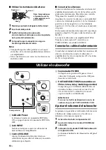
Page 7: ...ll outlets 1 Power indicator Lights up when the POWER switch is set to ON goes off when the POWER switch is set to OFF 2 INPUT jack Input jack for connecting the line level subwoofer output on your amplifier 3 VOLUME control Adjusts the volume of the subwoofer Turn it clockwise to increase the volume counterclockwise to decrease the volume 4 POWER switch Set this to ON to turn on the subwoofer Set...

Page 8: ...bles are not connected properly Make sure the speaker cables are connected properly The sound is very quiet The speaker cables are not connected properly Make sure the speaker cables are connected properly L left to L R right to R to and to Issue Possible cause Remedy The POWER switch is set to ON but the subwoofer doesn t work The power cable is not connected properly Set the POWER switch to OFF ...

Page 9: ... 48 kg 1 06 lbs NS C20 0 68 kg 1 50 lbs Subwoofer NS SW20 Type Advanced Yamaha Active Servo Technology Driver 16 cm 6 1 2 cone woofer non magnetic shielding type Amp output power 50 W 100 Hz 5 Ω 10 T H D Amp dynamic power 100 W 5 Ω Input impedance INPUT 1P RCA pin jack 10 kΩ Frequency response 30 Hz 160 Hz Input sensitivity INPUT 1P RCA pin jack 80 mV 50 Hz 50 W 5 Ω Power supply U S A and Canada m...

Page 10: ...dor de potencia incorporado sale calor del panel trasero Aleje la unidad de las paredes dejando un espacio mínimo de 20 cm por encima por detrás y a ambos lados de launidad para evitar que se produzca un incendio o daños Además no ponga la unidad con el panel trasero hacia abajo en el suelo o en otras superficies 5 Cuando utilice un humidificador asegúrese de evitar la condensación dentro de esta ...

Page 11: ...1 Instalar los altavoces frontales central y surround 2 Instalar el subwoofer 2 Instalar los altavoces en la pared 2 Conectar los altavoces 3 Diagrama de conexión 3 Conectar los cables de alimentación 4 Utilizar el subwoofer 4 Ajustar el volumen del subwoofer 4 Solucionar problemas 5 Especificaciones 6 Contenido del paquete Cable del altavoz 25 m x1 Debe cortarse en 5 partes para los altavoces fro...

Page 12: ...ue tenga que dividir las superficies de las paredes paralelas colocando estanterías etc en ellas Instalar los altavoces en la pared Puede instalar los altavoces en una pared de la manera siguiente 1 Fije los tornillos a una pared firme o en un soporte para la pared tal como se muestra a continuación Utilice tornillos autorroscantes de 3 5 a 4 mm de diámetro 2 Cuelgue cada altavoz por los orificios...

Page 13: ...bles pelados Notas El cable de los altavoces debe ser tan corto como sea posible No ate ni enrolle los cables excesivamente Trence los cables pelados firmemente para que los filamentos individuales no se separen Procure no lesionarse cuando prepare los cables de altavoz Conectar los altavoces ANTENNA FM GND AM COMPONENT VIDEO PR PB Y OPTICAL TV AV 1 AV 2 AV 3 AV 4 AV 5 AUDIO 1 AUDIO 2 COAXIAL CD C...

Page 14: ... el subwoofer conecte el subwoofer el amplificador y los otros componentes AV a las tomas de CA correspondientes 1 Indicador Power Se ilumina al ajustar el conmutador POWER a ON se apaga al ajustar el conmutador POWER a OFF 2 Jack INPUT Jack de entrada para conectar el subwoofer de nivel de línea en el amplificador 3 Control VOLUME Ajusta el volumen del subwoofer Gírelo en sentido horario para sub...

Page 15: ...roblema Posible causa Solución No hay sonido Los cables del altavoz no están conectados correctamente Compruebe que los cables de los altavoces estén conectados correctamente El sonido es muy bajo Los cables del altavoz no están conectados correctamente Compruebe que los cables de los altavoces estén conectados correctamente L izquierdo a L R derecho a R a y a Problema Posible causa Solución El co...

Page 16: ... Subwoofer NS SW20 Tipo Advanced Yamaha Active Servo Technology Driver Woofer con cono de 16 cm tipo blindado no magnéticamente Amplificador de potencia de salida 50 W 100 Hz 5 Ω 10 T H D Amplificador de potencia dinámica 100 W 5 Ω Impedancia de entrada INPUT jack de patilla 1P RCA 10 kΩ Respuesta de frecuencia 30 Hz 160 Hz Sensibilidad de entrada INPUT jack de patilla 1P RCA 80 mV 50 Hz 50 W 5 Ω ...

Reviews: